E6581595
F-66
6
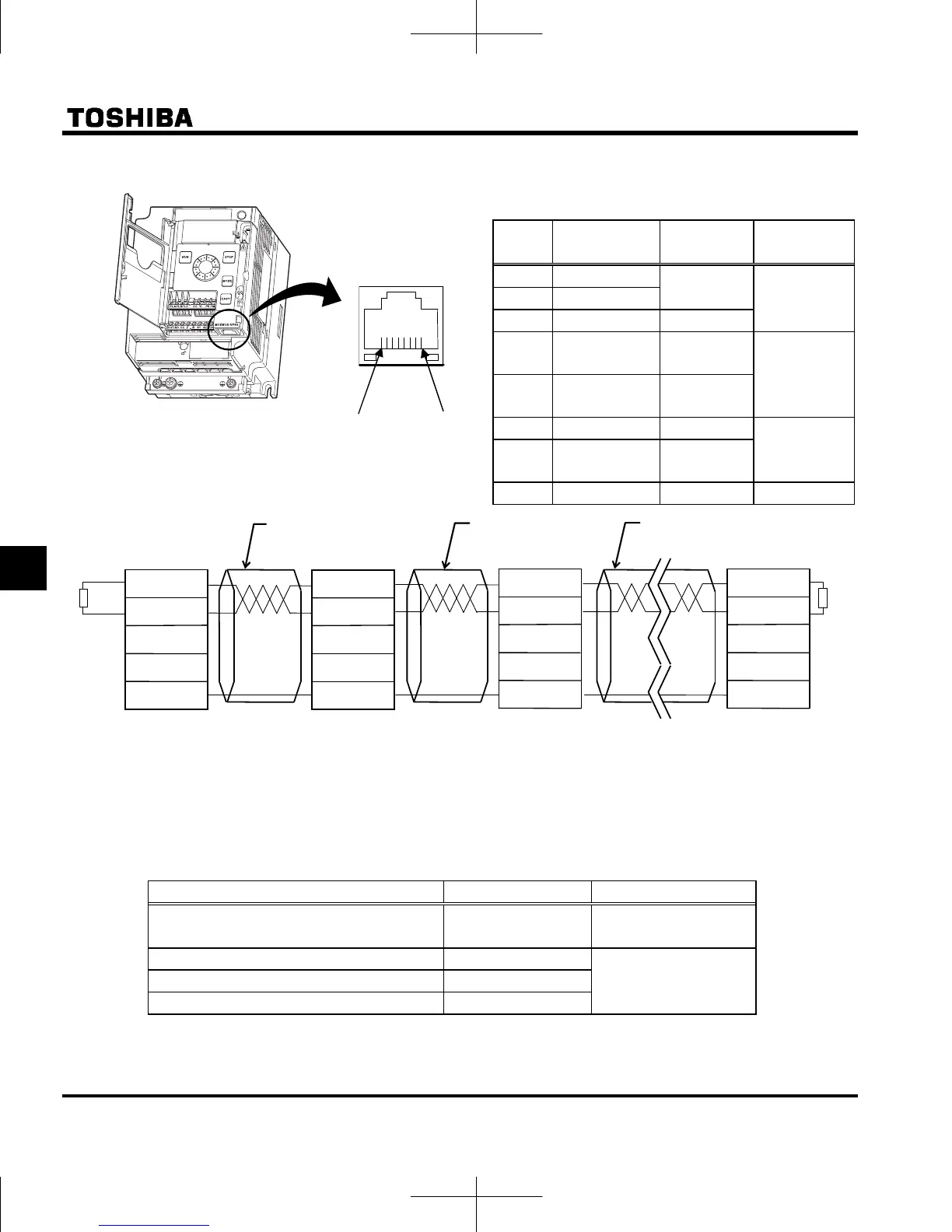
Configuration of RS485 connector and wiring
Pin
number
Name Description
RS485
communication
1 -
For factory
Do not connect 2 -
3 (SG) Ground
4
RXD+/TXD+
Same phase
reception data
Using
5
RXD-/TXD-
Anti-phase
reception data
6 - Open
Do not connect
7 P8
Power supply
for option
8 SG Ground Using
Connect only Pin-4, 5, 8 when manufacturing on the communication cable on the user side.
Never use pin-7. Note 1)
In case branch cables, use the terminal board or refer to following table.
Full length must be within 500m and stab length of branches must be within 1m each.
Examples of products available on the market (as of October 2010) Note 2)
Product Type Maker
Jack / jack type branch adaptor BJ8888W
SANWA DENKI
KOGYO CO.,LTD.
Branch connector BMJ-8
HACHIKO ELECTRIC
CO.,LTD.
Branch connector with termination resistor BMJ-8P
Rosette (additional 8 units) OMJ-88R
Note 1) Pin-7 provides power to the extension panel for option. Do not use this pin for RS485 communication.
Incorrect connect may result in the inverter malfunction or failure.
Note 2) All pins of these connectors are connected. Pull out pins except pin-4, 5, 8 by cable side.
Pin-1
Pin-8
Inverter viewed
from bottom
Master
RXD+/TXD+
RXD-/TXD-
SG
Pin-4
Pin-5
Pin-8
Straight
Straight
Termination resistor : 100 to 120Ω-1/4W or more
Straight
Slave
RXD+/TXD+
RXD-/TXD-
SG
Slave
RXD+/TXD+
RXD-/TXD-
SG
Slave
RXD+/TXD+
RXD-/TXD-
SG
Termination
resistor
Termination
resistor

 Loading...


