E6581595
M-4
13
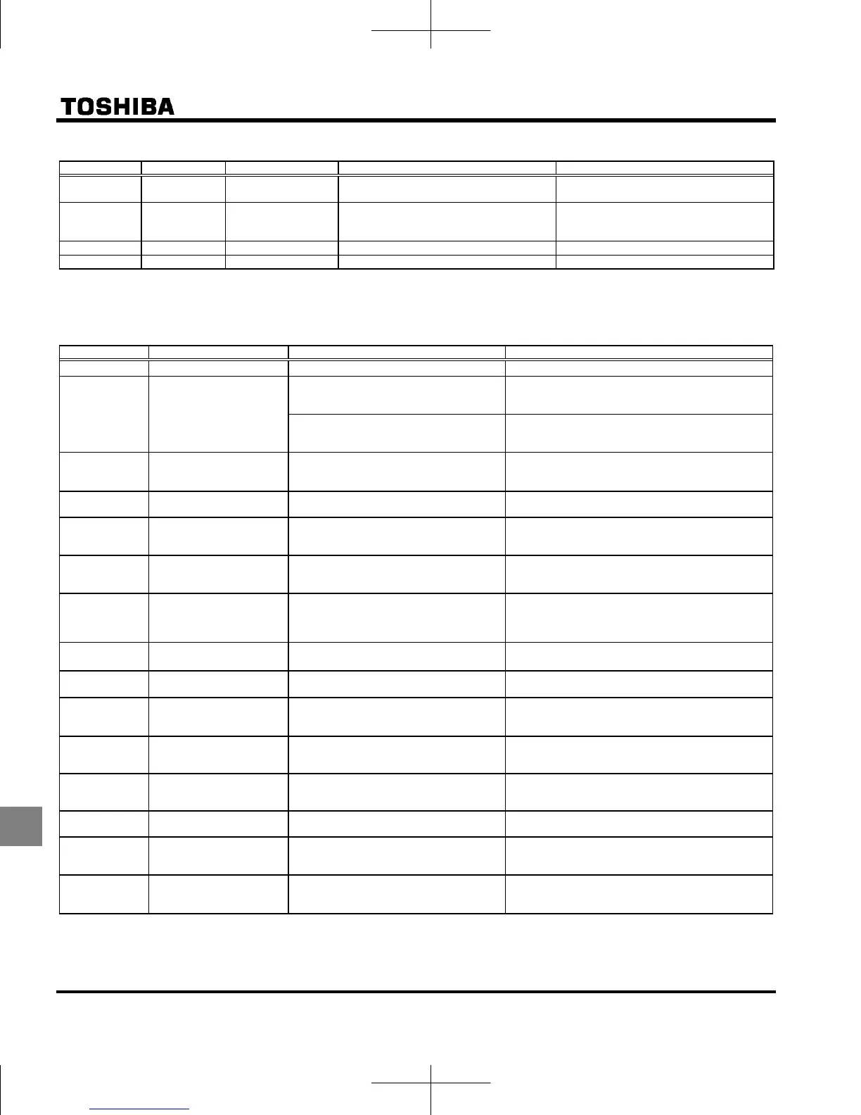
[Trip information]
Error code Failure code Name Description Remedies
0033 CPU communications
error
A communications error occurs between
control CPUs.
Contact your Toshiba distributor.
0034 Excessive torque
boosted
The automatic torque boost parameter
setting is too high.
The motor has too small impedance.
Set a lower automatic torque boost
parameter setting.
Make an auto-tuning.
0035 CPU fault 2
The control CPU is defective. Contact your Toshiba distributor.
003A CPU fault 3
The control CPU is defective. Contact your Toshiba distributor.
* You can select a trip ON/OFF by parameters.
[Alarm information] Each message in the table is displayed to give a warning but does not cause the inverter to trip.
Error code Name Description Remedies
ST terminal OFF
The ST-CC circuit is opened. Close the ST-CC circuit.
Undervoltage in main
circuit
The supply voltage between R, S and T is
under voltage.
Measure the main circuit supply voltage.
If the voltage is at a normal level, the inverter
requires repairing.
In case of single phase 120V class, the
shorting-bar between P0 and PA/+ is
removed.
Connect the shorting-bar between P0 and PA/+.
Retry in process
The inverter is in process of retry.
A momentary stop occurred.
The motor speed is being detected.
The inverter restarts automatically. Be careful of the
machine because it may suddenly restart.
Frequency point setting
error alarm
The frequency setting signals at points 1
and 2 are set too close to each other.
Set the frequency setting signals at points 1 and 2
apart from each other.
Clear command
acceptable
This message is displayed when pressing
the STOP key while an error code is
displayed.
Press the STOP key again to clear the trip.
Emergency stop command
acceptable
The operation panel is used to stop the
operation in automatic control or remote
control mode.
Press the STOP key for an emergency stop.
To cancel the emergency stop, press any other key.
/
Setting error alarm /
An error code and data are
displayed alternately twice
each.
An error is found in a setting when data is
reading or writing.
Check whether the setting is made correctly.
/
Display of first/last data
items
The first and last data item in the
data group is displayed.
Press MODE key to exit the data group.
DC braking
DC braking in process The message goes off in several tens of seconds if
no problem occurs.
Note 1)
Flowing out of excess
number of digits
The number of digits such as frequencies
is more than 4.
(The upper digits have a priority.)
Lower the frequency free unit magnification .
Deceleration stop during
power failure function
activated.
The deceleration stop during power
failure with is activated.
To restart operation, power supply reset or input an
operation signal again.
Auto-stop because of
continuous operation at
the lower-limit frequency
The automatic stop function selected with
was activated.
This function is cancelled, when frequency reference
reaches LL+0.2Hz or operation command is OFF.
Parameters in the process
of initialization
Parameters are being initialized to default
values.
Normal if the message disappears after a while
(several seconds to several tens of seconds).
Output frequency upper
limit
An attempt was made to operate at a
frequency higher than 10 times the base
frequency ( or ).
Operate at a frequency within 10 times the base
frequency.
Operation panel key alarm
The RUN or STOP key is held down for
more than 20 seconds.
The RUN or STOP key is faulty.
Check the operation panel.
Note 1) When the ON/OFF function is selected for DC braking (DB), using the input terminal selection parameter,
you can judge the inverter to be normal if “” disappears when opening the circuit between the terminal and CC.

 Loading...


