E6581595
M-5
13
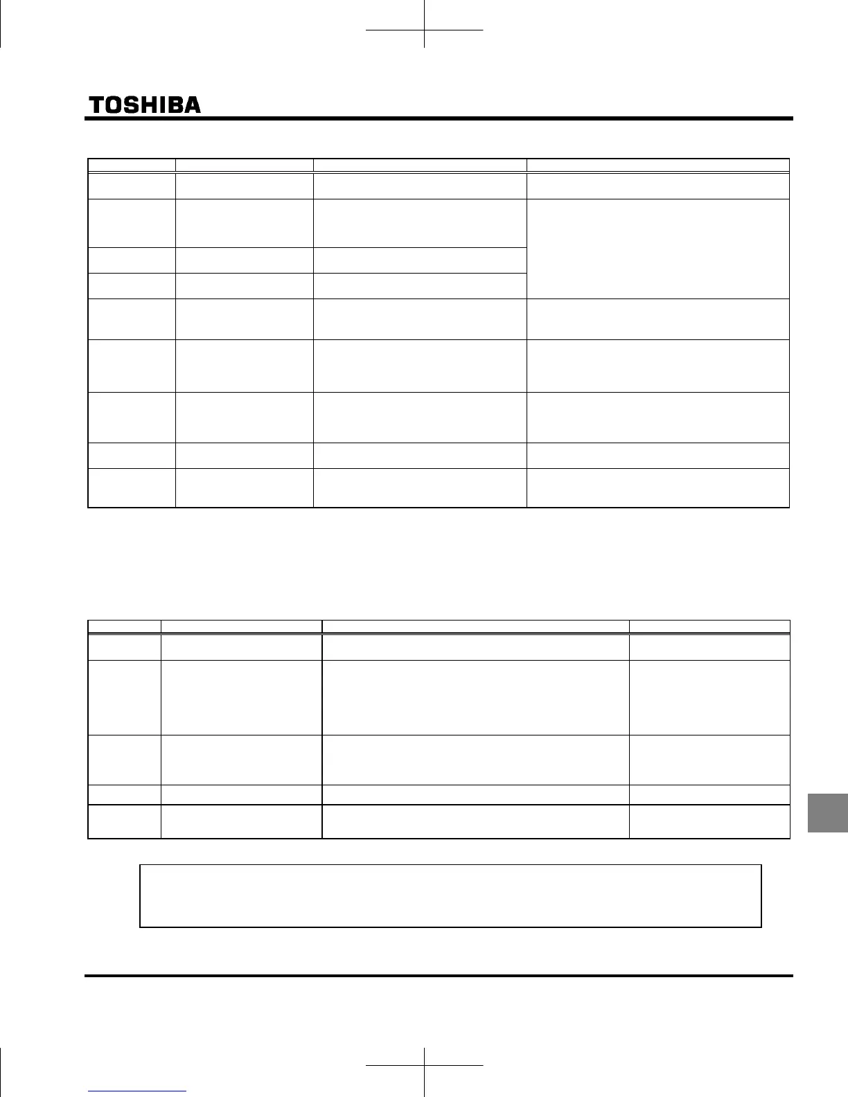
[Alarm information] Each message in the table is displayed to give a warning but does not cause the inverter to trip.
Error code Name Description Remedies
Auto-tuning
Auto-tuning in process Normal if it the message disappears after a few
seconds.
External power supply
input
logic switching check
alarm
The input terminal was switched to sink
logic of external power supply input
(+24V).
After removing connection of the control circuit
terminals reset or turn the power off and then back
on again. This switches the logic.
Source logic switching
check alarm
The input terminal was switched to
source logic.
Sink logic switching check
alarm
The input terminal was switched to sink
logic.
/
Password verification
result
After the password setting (f738), the
password was input to f739 (password
verification).
If the password is correct, pass is displayed and
if it is incorrect, fail is displayed.
/
Switching display of
Easy setting mode /
Standard setting mode
The EASY key was pushed in the
standard monitor mode.
When easy is displayed, setting mode becomes
easy setting mode. When std is displayed, it
becomes standard setting mode.
Note 2)
Input requirement of region
setting
Power was supplied to the inverter at first
time
Set the parameter set to 0.
Set the parameter typ to 13.
Set a region setting by using setting dial.
Refer to section 3.1.
No trip of past trip
No new record of past trip, after past trips
were clear.
Normal operation.
No detailed information of
past trip
The detailed information of past trip is
read by pushing the center of setting dial
during blinking nerr ⇔ number.
Normal operation.
To be returned by pressing MODE key.
Note 2) is blinking when setup menu starts. Key operation is not allowed.
But parameter set doesn’t blink as same as other parameters.
[Pre-alarm information] Each message in the table is displayed to give a warning but does not cause the inverter to trip.
The following error code and the frequency will flash alternately.
Error code Name Description Remedies
Overcurrent pre-alarm
When a current flows at or higher than the over current stall
prevention level.
Same as (overcurrent)
Overvoltage pre-alarm
When a voltage is generated at or higher than the over voltage
stall prevention level.
When a voltage is generated at or higher than the over voltage
stall prevention level.
Even if it was lower than the over voltage stall prevention level,
when a voltage is generated at sharp increse.
Same as (overvoltage)
Overload pre-alarm
When the cumulative amount of overload reaches 50% or
more of the overload trip value.
When the main circuit element temperature reaches the
overload pre-alarm level.
Same as (overload)
Overheat pre-alarm
When the overheat protection pre-alarm level is reached.
Same as (overheat)
Communication pre-alarm
When the communication was broken off at or higher than the
over parameter f803 setting.
Same as err5 (communication
fault)
If two or more problems arise simultaneously, one of the following pre-alarms appears and blinks.
, ,
The blinking alarms , , , h, t are displayed in this order from left to right.

 Loading...


