E6581595
A-17
1
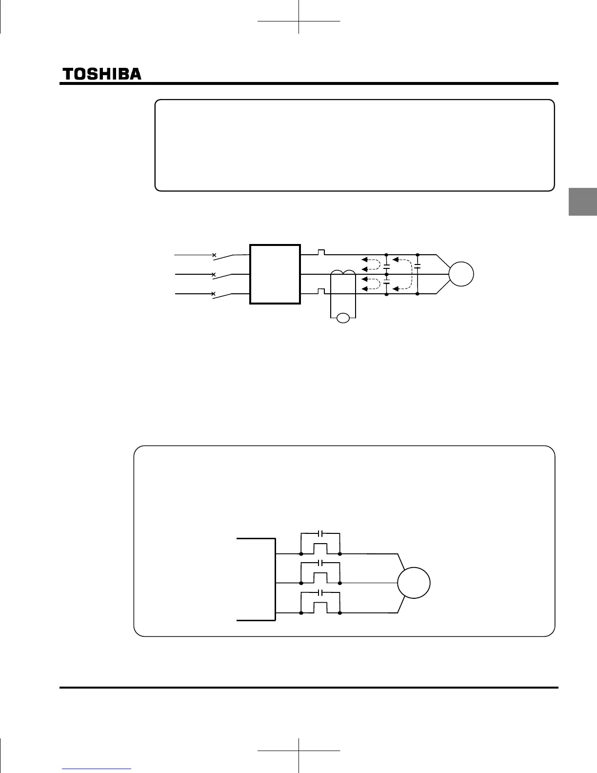
(3) Influence of leakage current across lines
Power
supply
Inverter
Thermal relays
CT
A
IM
Leakage current path across wires
(1) Thermal relays
The high frequency component of current leaking into electrostatic capacity between inverter out-
put wires will increase the effective current values and make externally connected thermal relays
operate improperly. If the wires are more than 50 meters long, it will be easy for the external
thermal relay to operate improperly with models having motors of low rated current (several
A(ampere) or less), because the leakage current will increase in proportion to the motor rating.
Remedies:
1. Use the electronic thermal built into the inverter. (Refer to section 3.5)
The setting of the electronic thermal is done using parameter , .
2. Reduce : PWM carrier frequency. However the motor magnetic noise is increased. (Refer to
section 6.11)
3. This can be improved by installing 0.1μ~0.5μF - 1000V film capacitor to the input/output terminals of
each phase in the thermal relay.
Remedies:
1. If there is no radio-frequency interference or similar problem, detach the built-in noise filter
capacitor, using the grounding capacitor disconnecting switch. (Refer to section 1.3.3-2))
2. Reduce : PWM carrier frequency. However the motor magnetic noise is increased.
(Refer to section 6.11)
.
hi
h fr
n
r
m
i
l
r
f
r
r
h l
k
r
k
r
U/T1
V/T2
W/T3
IM
Thermal rela
s

 Loading...


