E6581595
C-17
3
1) Setting the electronic thermal protection characteristics selection and
motor electronic thermal protection level 1 , 2
The electronic thermal protection characteristics selection is used to enable or disable the motor
overload trip function () and the overload stall function.
While the inverter overload trip () will be in constant detect operation, the motor overload trip ()
can be selected using the parameter
Explanation of terms
Overload stall: This is an optimum function for equipment such as fans, pumps and blowers with
variable torque characteristics that the load current decreases as the operating speed
decreases.
When the inverter detects an overload, this function automatically lowers the output
frequency before the motor overload trip is activated. With this function,
operation can be continued, without tripping, by operating using a frequency balanced
by load current.
Note: Do not use the overload stall function with loads having constant torque characteristics (such as
conveyor belts in which load current is fixed with no relation to speed).
[Using standard motors (other than motors intended for use with inverters)]
When a motor is used in the lower frequency range than the rated frequency, that will decrease the cooling
effects for the motor. This speeds up the start of overload detection operations when a standard motor is
used in order to prevent overheating.
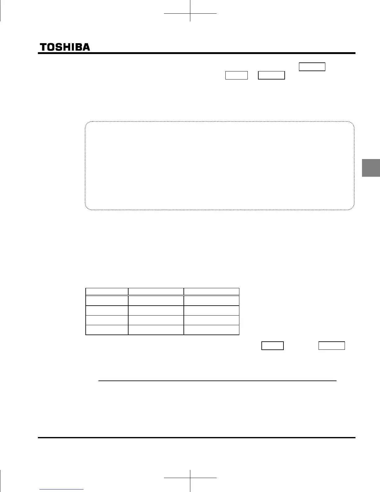
Setting of electronic thermal protection characteristics selection
Setting value Overload protection Overload stall
valid invalid
valid valid
invalid invalid
invalid valid
Setting of motor electronic thermal protection level 1 (Same as f173)
When the capacity of the motor in use is smaller than the capacity of the inverter, or the rated current of
the motor is smaller than the rated current of the inverter, adjust thermal protection level 1 for the
motor in accordance with the motor's rated current.
* When displaying as a percentage, 100% = rated output current (A) of the inverter is displayed.

 Loading...


