16502 PIREG-C2 Gerätebeschreibung mit EtherNet_IP Bussystem191017 - EN.docx/ Page 7 of 66
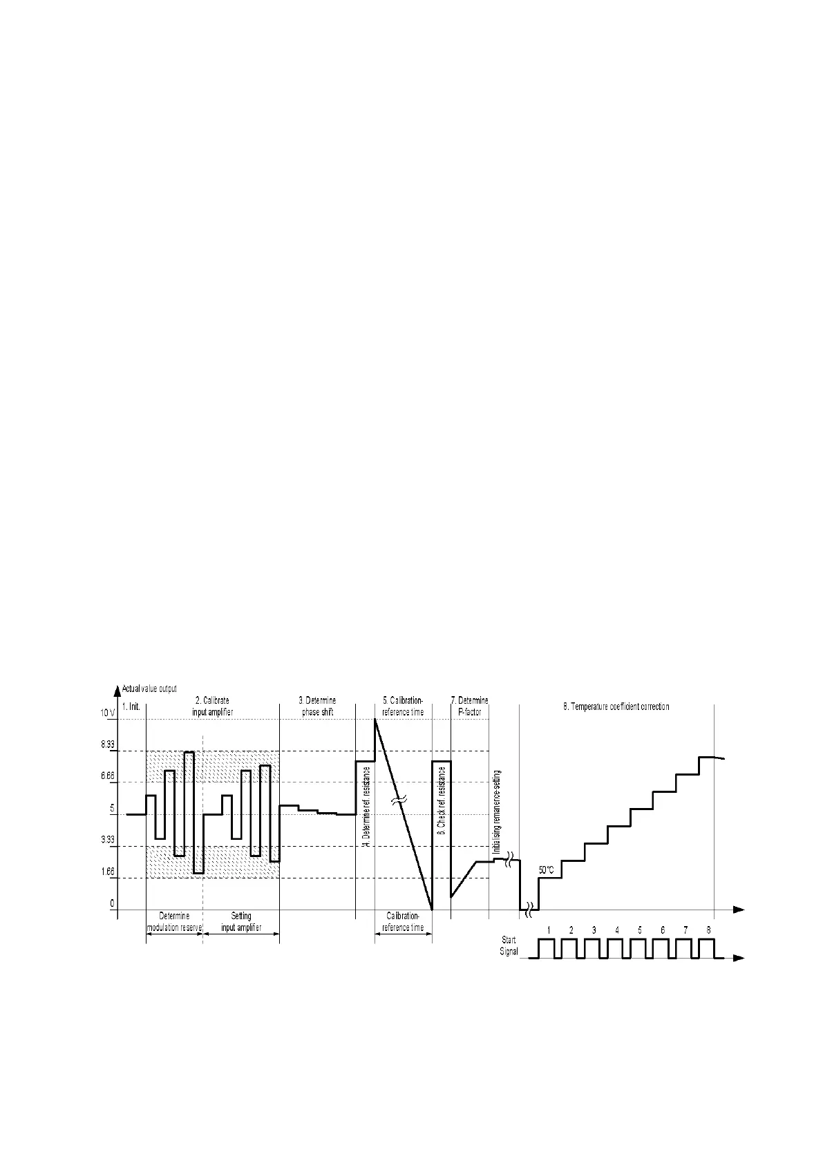
In calibration stage 8, the PIREG-C2 gradually heats up the heating conductor in eight temperature in-
crements or stages. The PIREG-C2 compares its actual value temperature with the actual temperature of
the heating conductor, which it receives as a target value or directly as a measured temperature value.
The size of each increment is a result of the selected temperature range. The first temperature increment
is always 50 °C. The temperature of the eighth temperature increment falls 20% below the final value of
the temperature range. The six other temperature increments are equidistant between these points. For
the300 °C temperature range, this results in the following temperatures: 50, 77, 104, 131, 159, 186, 213
and 240 °C. For the 500 °C temperature range, this results in the following temperatures: 50, 100, 150,
200, 250, 300, 350 and 400 °C.
The actual temperature of the heating conductor must be sent back externally to the PIREG-C2 as a tar-
get value or directly as a measured value of the TM6 thermometer. Deviations of up to ±20 % between
the calculated actual value temperature and the actual temperature of the heating conductor can be cor-
rected ( 4.1.9., 4.7. and 4.11.). The correction process is controlled with the “Start” signal or by com-
mand (STST).
The 8-point Tc correction can be saved by command (STKA) so that it doesn't need to be repeated after
a new calibration but only when the heating conductor is replaced.
Performing the 8-point Tc correction:
- manual operation: The actual temperature of the heating conductor is reported back to the PIREG-C2
via the set value input. The next temperature step is switched to with the rising edge of the “Start” signal.
After the heating conductor has reached a uniform temperature the temperature set as the target value is
taken over as the actual temperature of the heating conductor with the falling edge of the “Start” signal.
After heating to the next temperature stage, only accept the temperature once the heating conductor itself
has reached the specified temperature. The actual value output indicates the corresponding, not yet cor-
rected actual value temperature of the PIREG-C2.
At the beginning of the 8-point Tc correction, the "Calibration" LED flashes for 5 seconds at a cycle rate of
1 Hz, while the PIREG-C2 tries to establish the connection to the TM6 thermometer.
- manual operation with the TM6 thermometer: The 8-point Tc correction is controlled with the “Start”
signal as described above. The actual temperature of the heating conductor is measured with the TM6
thermometer which is connected to the RS232 interface of the PIREG-C2. The PIREG-C2 automatically
tries to establish a connection with the TM6 thermometer for 5 seconds at the beginning of the 8-point Tc
correction. The "Calibration" LED flashes at a cycle rate of 1 Hz during connection establishment and
when the connection to the TM6 thermometer has been established.
- automatic 8-point Tc correction: The PIREG-C2 must be connected to the TM6 thermometer and the
set value for the heating time must be greater than zero for the automatic 8-point Tc correction. The heat-
ing time is the period until the heating conductor has reached a uniform temperature at a temperature
stage. The heating time is set either in the Reset state or by command (KTKZ) ( 4.7. and 4.8.). The
PIREG-C2 undergoes the automatic 8-point Tc correction independently and remains at each tempera-
ture stage for the preset heating time.
Figure 1: Calibration process
The controller must undergo calibration steps one to seven for each calibration. Step eight is a selectable
calibration function ( 3.1.8.). If an error occurs during the individual calibration steps, the PIREG-C2
stops the calibration process and then restarts the calibration. Calibration is stopped with an error mes-
sage after attempt five was not successful ( 3.4.).
Calibration must be carried out when the heating conductor has reached a temperature of approx. 20 °C
or the externally determined calibration temperature to ensure that the R20 reference resistance of the