10 Threat Protection System Hardware Specification and Installation Guide
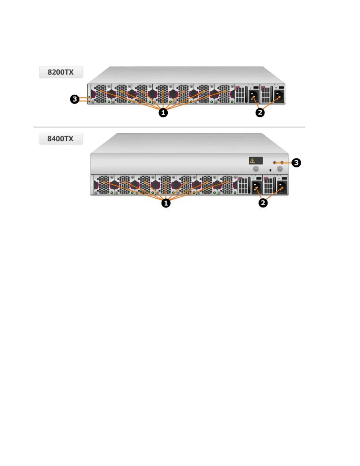
Figure 5. TPS TX Series devices – rear panel
1. Fan modules - fans are numbered from left to right (Fan 1 is on the left; Fan 7 is on the right)
2. Power supply modules (Power supply 1 is on the left; Power supply 2 is on the right)
3. DC grounding lug screw holes
Chassis – features
The TPS TX Series chassis features include the following elements:
• Power button on page 10
• Chassis LEDs on page 12
• Fans and power supplies on page 11
• External storage card on page 23
• Ports on page 23
Power button
The power button is located on the right side of the console/management ports on the front panel. The
power button light indicates the current status of the appliance.
• No light — Appliance is powered off.
• Green — Appliance is powered on.
 Loading...
