Threat Protection System Hardware Specification and Installation Guide 29
5. Alert indicator
6. System status indicator
7. Power indicator
Chassis – rear panel
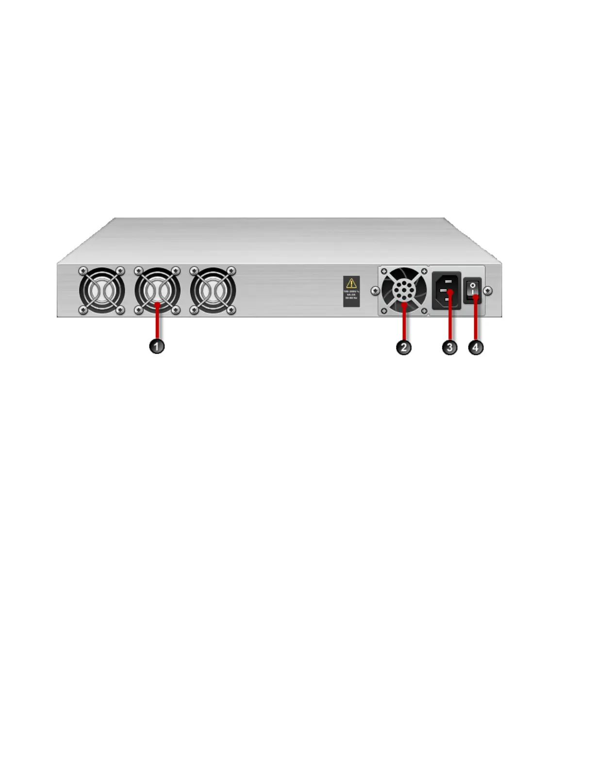
The following illustration shows a rear-panel view of a 440T device.
Figure 11. TPS 440T device – rear back panel
1. Fans (3)
2. AC power supply
3. AC power connector
4. Power switch
Chassis – features
The TPS 440T chassis features include the following elements:
• Power switch and power indicator on page 29
• System status indicator on page 30
• Alert indicator on page 30
• Fans and power supplies on page 30
• External storage card on page 30
• Ports on page 30
Power switch and power indicator
The power switch is located on the right side of the back panel. The power indicator on the front panel
indicates the current power status of the device.