Step 2: Attaching the claws Assembling the X/Y axes 31
8 x
12 x
4 x 24 x
4 x
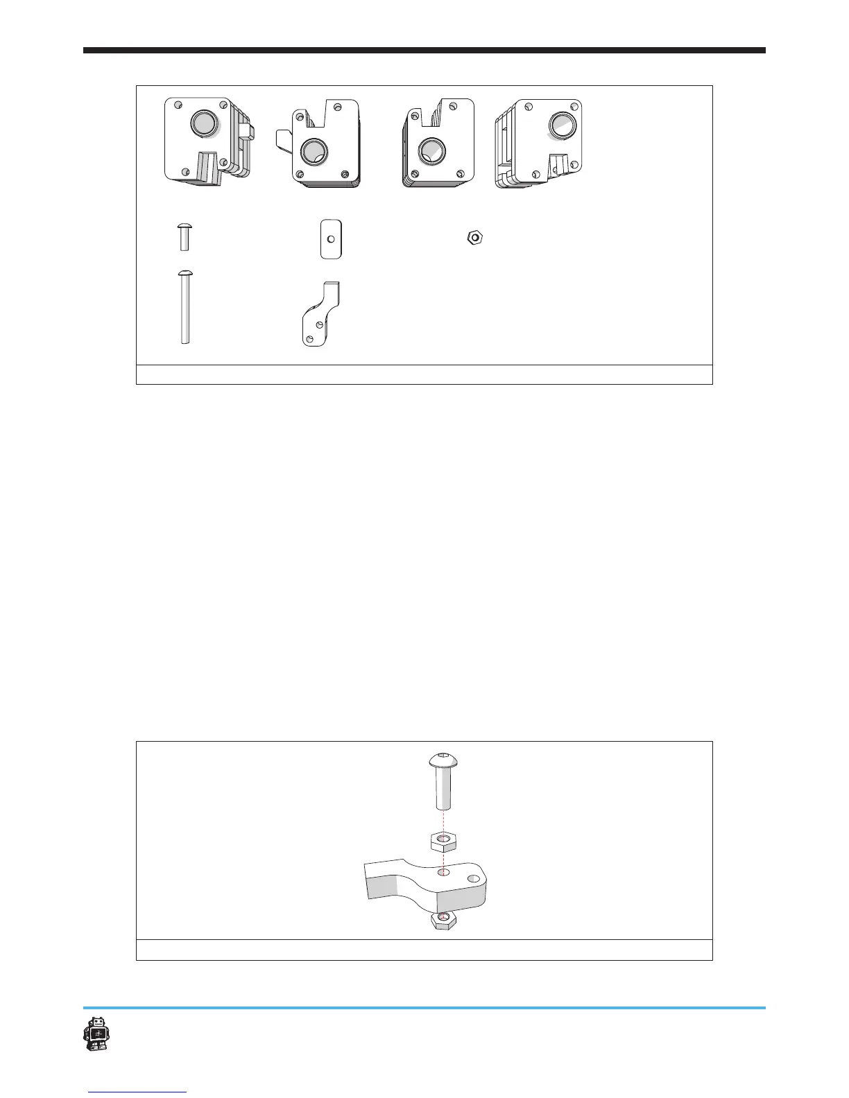
image 27: parts needed for this step
To attach the claws, perform the following actions:
1. Attach the bolt to the wooden part marked C, see image 28.
Use one bolt M3 x 10mm and two hex nuts 3mm.
5 Notice: the last hex nut will barely t in. This is normal.
2. Place the wooden part marked C in the FRONT slider block.
3. Place three bolts M3 x 30mm, see image 29.
4. Attach the nuts, see image 29.
5 Notice: do not tighten the nuts too much. The claw must be able to
rotate.
5. Repeat action 1-5 three times to attach all wooden parts marked C on
all slider blocks.
6. Assemble the wooden parts, marked FRONT C, RIGHT C,
LEFT C and BACK C, see image 30.
Use one bolt M3 x 10mm and one nut.
5 Notice: this assembled wooden parts, marked C will be used later.
image 28: attaching the bolt to the wooden part marked C
A
B C D
E F
FRONT LEFT RIGHT BACK slider blocks
 Loading...