60
6.4.2. Step 2: Assembling the Heated bed PCB
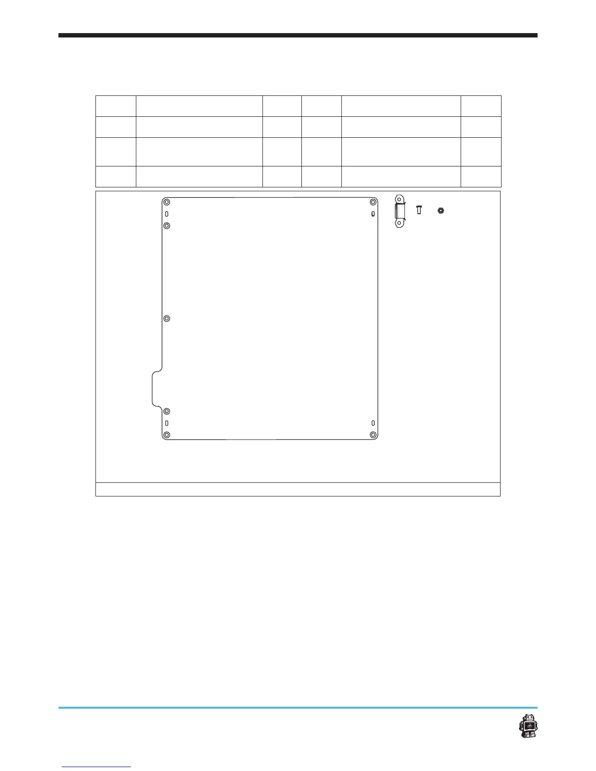
The following parts are needed in this step.
Letter Description Qnty. Letter Description Qnty.
A
Heated bed PCB 1
C
Heated bed Cable 1
B
Countersunk Bolts
M3x8
4
D
Glass Retainer Clip 2
E
Lock Nut M3
image 74: parts needed for this step
To assemble the Heated bed PCB, perform the following actions (
1. Take the 2 glass retainer clips and place them on the back side of the
PCB. See image 75.
2. Use the 4x M3x8mm countersunk bolts and 4x M3 Locknuts to bolt it
down.
3. Place the Heated bed PCB with the aluminum side down on a at
surface.
4. Connect the Heated bed cable to the Connector on the Heated bed.
See image 76
5. The Gray (FAT) wires go on the left side and the black (THIN) wires go
on the right side.
A
B
E
C
D





 To Next Page