Step 1: drive mechanism main body assembly Assembling the material feeder 71
6.5.1. Step 1: drive mechanism main body assembly
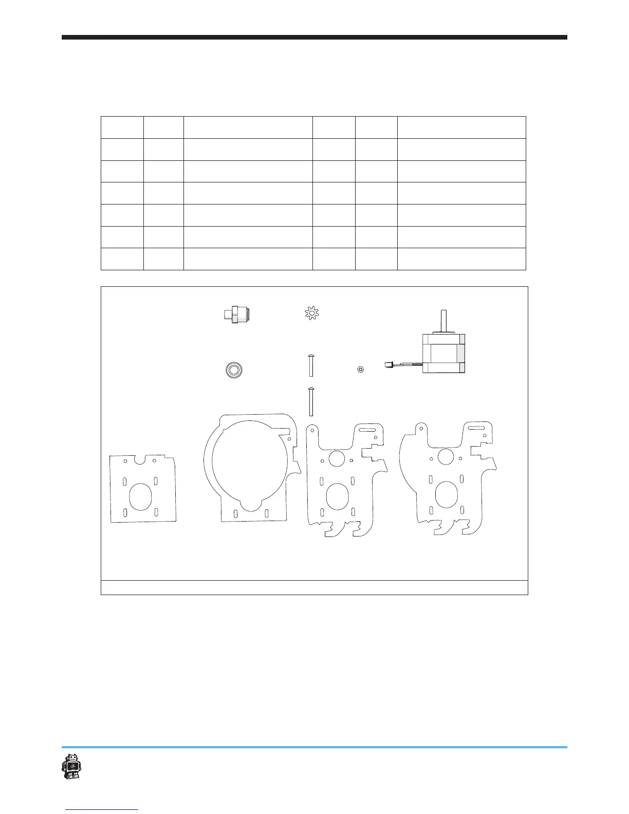
The following parts are needed in this step.
Letter Qnty. Description Letter Qnty. Description
A
1 wooden part 10A
G
1 stepper motor
B
1 wooden part 10B
H
2 hex nuts 3mm
C
1 wooden part 10C
I
5 bolts M3 x 20mm
D
1 wooden part 10D
J
2 bolts M3 x 25mm
E
1 small black gear
K
2 ball bearings 8mm
F
1 quick t coupling
image 87: parts needed for this step
To assemble the extrusion head housing, perform the following actions.
1. Move the small black gear over the motor axis, see image 88.
5 Notice: make sure the small black gear is placed on the top motor axis,
so the motor axis does not sticks out.
2. Place a ball bearing 8mm in the hole of the wooden part 10A.
3. Place a ball bearing 8mm in the hole of the wooden part 10C, see
image 89.
AB CD
EF G
HI
J
K