Step 1: assembling the UltiController Assembling and connecting the UltiController 93
6.7.1. Step 1: assembling the UltiController
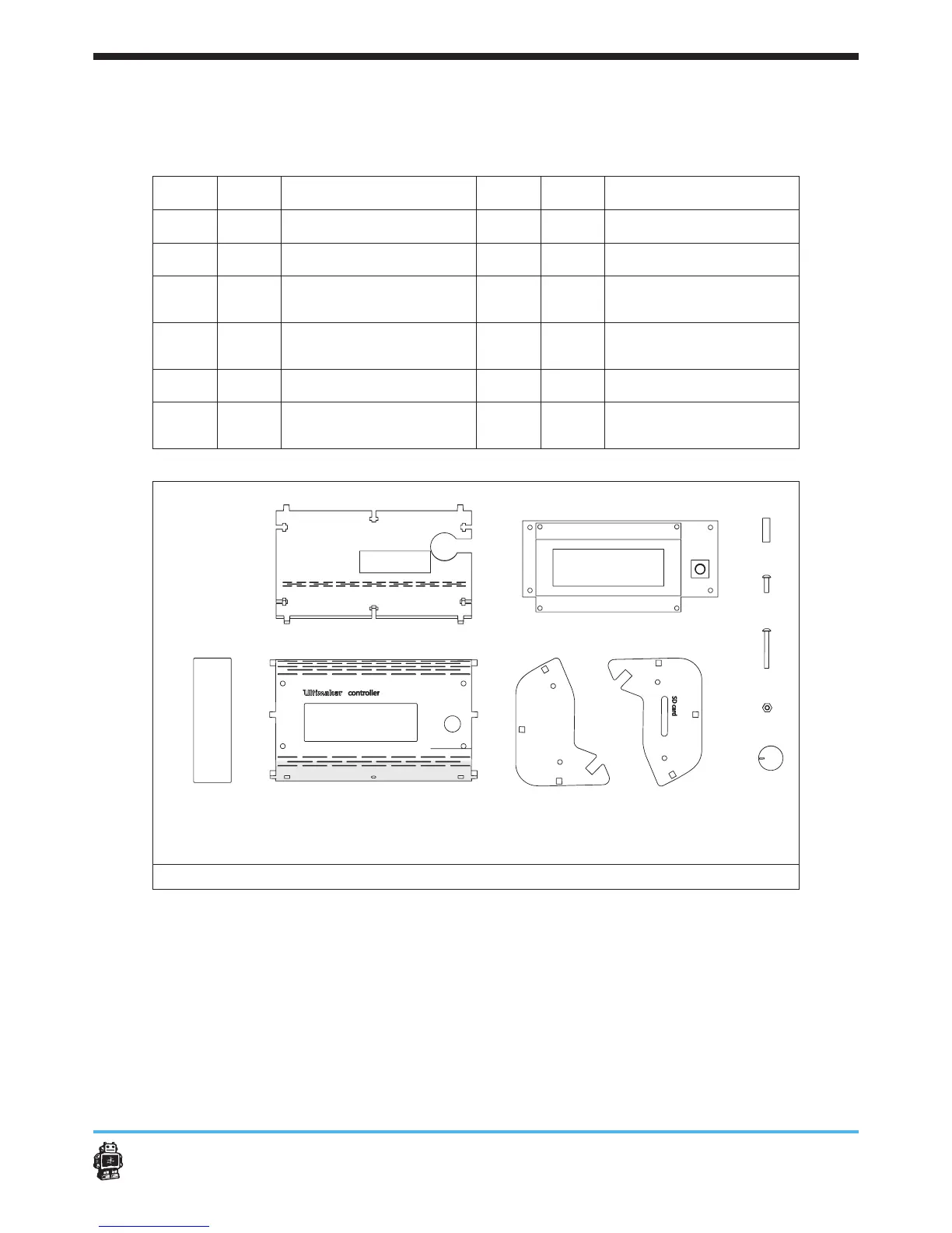
The following parts are needed in this step.
Letter Qnty. Description Letter Qnty. Description
A
1 UltiController BACK
G
1 UltiController LEFT
B
1 display v1.0
H
1 UltiController RIGHT
C
4 tube spacer
I
4
Nylon bolts M3 x
25mm
D
4
Nylon bolts M3 x
12mm
J
10 hex nuts 3mm
E
1 UltiController FRONT
K
1 button
F
1 UltiController window 1
UltiController PCB
Connection Cable
image 110: parts needed for this step
To assemble the UltiController, perform the following actions.
1. Remove the foil from the display V1.0 (if present).
2. Remove the protective sticker from the piezo speaker (if present).
3. Place UltiController FRONT facing down and place the acrilic window
in the cutout.
4. Attach the display v1.0 to the UltiController FRONT, see image 111.
Use four bolts M3 x 25mm, four tube spacers and four hex nuts 3mm.
A B C
D
EF
G
H
I
J
K