Step 4: Mounting the axes Assembling the X/Y axes 37
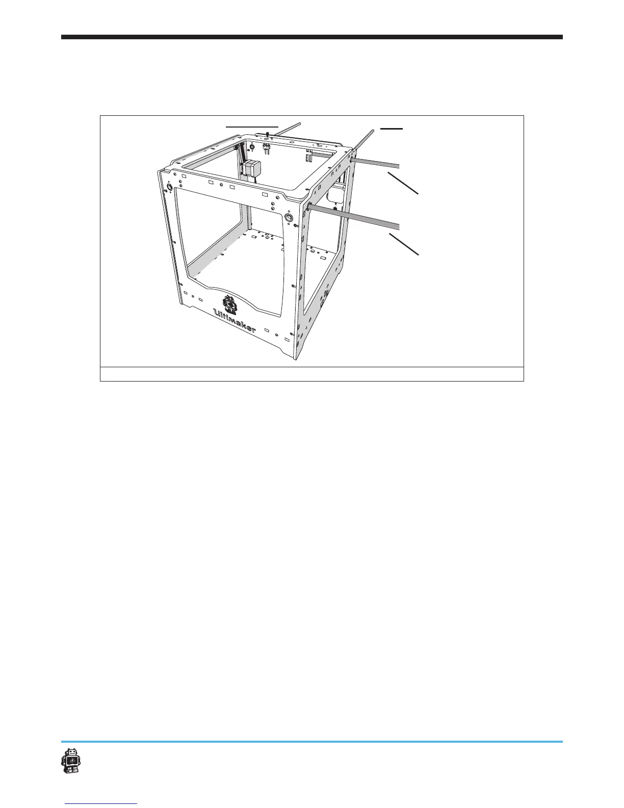
To help you performing the actions, the following overview is provided, see
image 38.
BACK
RIGHT
LEFT
FRONT
image 38: overview of the LEFT, RIGHT, BACK and FRONT axes
To attach axis FRONT (SHORT) perform the following actions:
1. Get axis SHORT
2. Rotate the wooden end cap WITHOUT hole (RIGHT panel, FRONT), see
image 39.
3. Put the pulleys on the timing belts.
Use ONE timing pulleys for each timing belt.
5 NOTICE: the thinnest side of the timing pulley is facing to the outside.
4. Move the axis SHORT from the RIGHT panel to the LEFT panel, see
image 41.
Place the following ve parts, in order, on the axis SHORT:
- timing belt with ONE timing pulley.
- FRONT slider block.
5 NOTICE: the clamp of the FRONT slider block is facing downwards
along the FRONT panel, see image 40.
- timing belt with ONE timing pulley.
5. Rotate the wooden end cap WITHOUT hole (RIGHT panel, FRONT)
back to its normal position.
6. Attach the wooden end gap WITHOUT hole with a bolt M3 x 16mm and
a hex nut 3mm.
 Loading...