Step 2: drive bolt assembly Assembling the material feeder74
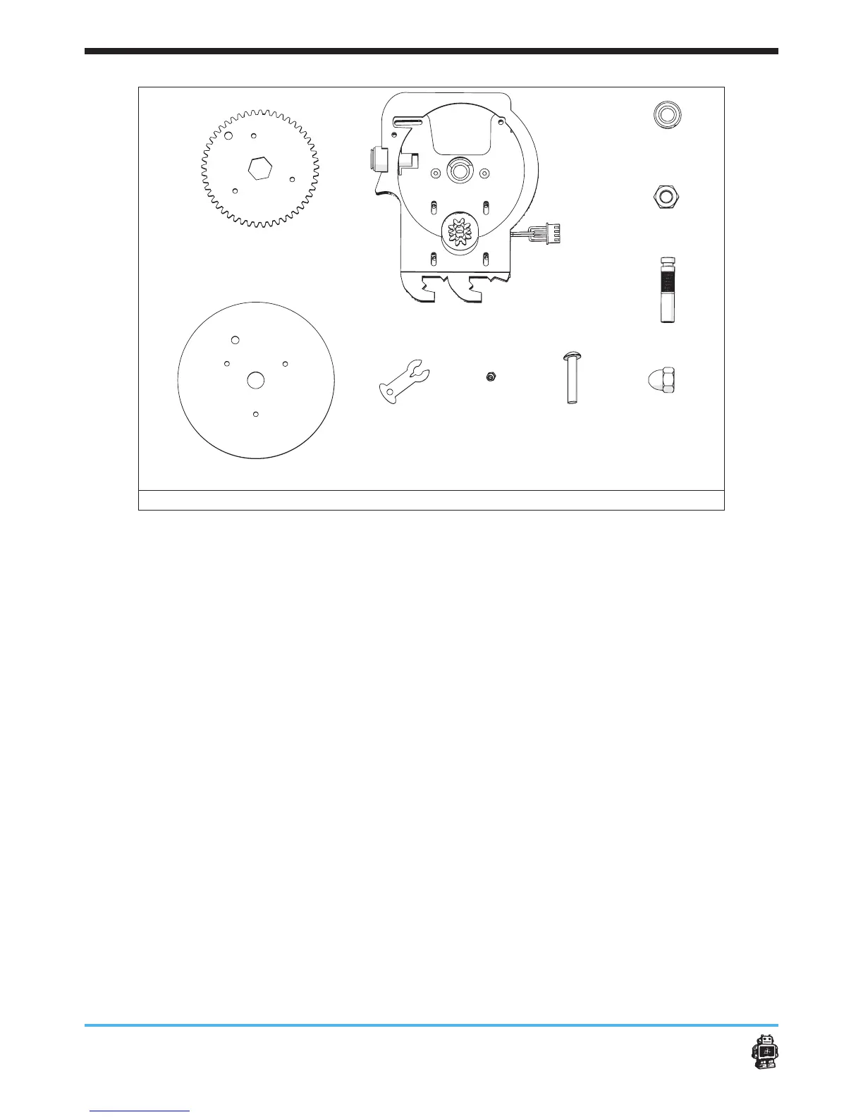
image 91: parts needed for this step
To make the drive bolt assembly, perform the following actions.
(for action 1-9 see image 101 and image 92)
1. Place the delrin clip on the groove of the hobbed bolt.
2. Move the hobbed bolt through the ball bearings 8mm.
5 Notice: check if the ‘good’ gripping part of the drive bolt is positioned
straight between the two wooden parts. If not, consider to attach the
wooden parts of the drive mechanism main body a little more tight.
3. Place the hex nut M8 inside the wooden gear.
4. Place the Wooden gear cap over the wooden gear, make sure to line
up the 4 holes.
5. Bolt them together with 3x M3x14mm bolts and 3x Locknuts. Make
sure the locknuts are on the engraved side of the wooden gear cap.
6. Place two washers M8 over the hobbed bolt. Between the bearing and
the wooden gear.
7. Attach the wooden gear on the hobbed bolt
5 Notice: Do not attach too tight. Check if the gear can rotate freely in
the ball bearings 8mm.
8. Place the cap nut M8 loosely on the hobbed bolt.
9. Now carefully tighten the cap nut M8 and the wooden gear. Be sure
the hobbed bolt is able to rotate in the ball bearings 8mm.
5 Notice: do not force!
10. Check if the motor with the small black gear makes contact with the
wooden gear. Adjust if necessary.
A
B
C D E
F
G
H
I