23
UltiMaker S8 Installation and user manual
4.9 Calibrations
The UltiMaker S8 is a high-speed dual-extrusion printer with a unique nozzle lifting system. For accurate dual-
extrusion prints, the XY offset and the position of the switch bay must be calibrated. Additionally, this printer
features an accurate active leveling system for optimal Z calibration. This section contains information about all
calibration processes.
Caution: When performing any of these calibration procedures, always keep hands clear of the build volume
until all components have stopped moving.
XY calibration
The horizontal distance between the nozzles of the two print cores in the X and
Y directions needs to be configured. A correct XY calibration will ensure that
the two colors or materials align well. The print cores that are supplied with the
UltiMaker S8 are already calibrated. For any new combination of print cores,
an XY offset calibration must be performed. The printer will then store this
calibration value internally.
Ensure two print cores and materials are installed before starting the calibration.
You will also need the XY calibration guide as a reference.
For the Material Station, ensure there is at least one material pre-loaded
for each extruder.
Start this calibration when prompted, or, in the Options menu, go to Maintenance
→ Print head → Calibrate XY offset and select Start calibration. The display and
the calibration sheet provide instructions, or go to ultimaker.com/xycalibration to
learn more about this process.
1. The UltiMaker S8 will print a grid pattern with both extruders. Wait
until it is complete.
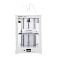
2. When the print is finished and the build plate has cooled down, remove the
flexible build plate from the printer.
Tip: See the XY calibration sheet as a reference; it shows which grids
correspond to X and Y and indicates the numbers for the printed lines.
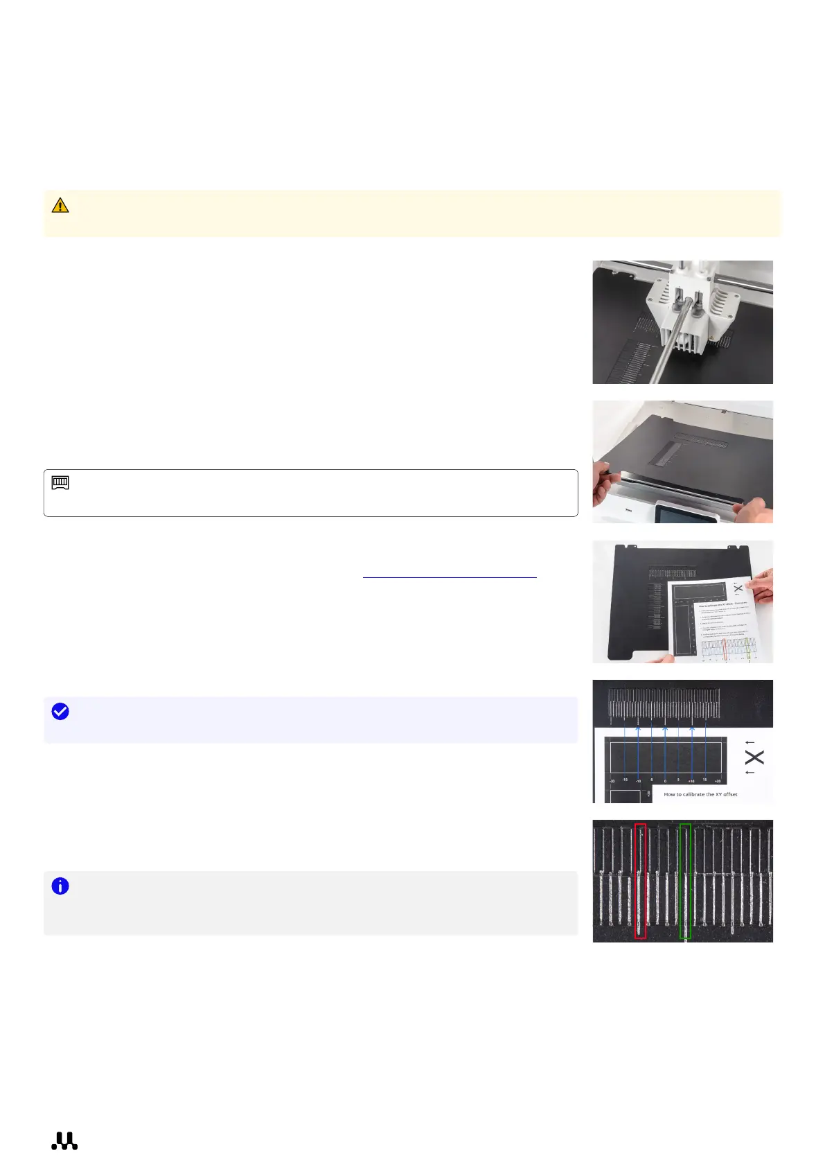
3. Find the best-aligned lines on the printed X grid and note which
number corresponds to these lines. Enter this number as the X offset
value on the display.
4. Repeat this for the Y grid and enter the value on the display.
5. After completing the XY calibration, place the flexible build plate
back into the printer.
Note: It is important that the printed XY offset pattern adheres well to the
build plate and shows no signs of under-extrusion. If it did not print well, it is
recommended to repeat the calibration print.