CHAPTER 2_______________________________________________________ PRODUCT DESCRIPTION
VAISALA __________________________________________________________________________ 5
The function Pws(T) is well known from literature. Thus, it is
possible to determine the offset (RH
0
) if measurements are made at
two or (preferably) more temperatures assuming a constant Pw
during the process.
30°C
20°C
-0.3
-0.2
-0.1
0
0.1
0.2
0.3
0 0.005 0.01 0.015 0.02 0.025 0.03 0.035 0.04 0.045
1/Pws(T)
RHout(%)
FIGURE 2-1 Device output during hypothetical offset calibration
cycle.
For example, for a transmitter with a -0.2%RH offset error is made 11
measurements at temperatures 20...30 °C. The frostpoint is assumed to
stay constant at -40 °C and that the 'Gain' is nominal 100%.
As the temperature increases the RH drops. Since the response is
linear, a straight line is fitted through the data points. The line
intercepts the y-axis at RH
0
as shown in FIGURE 2-1. Now the RH
0
is
known and it can be subtracted from the indicated value 0.35% RH to
get the correct value of 0.55% RH.
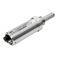
FIGURE 2-2 shows the DRYCAP
sensor as mounted on a DMP248
probehead. Through a combination of the polymer sensor and Pt 100
sensor, the DRYCAP
will accurately measure the water vapor
pressure used in determining low dewpoints.
During auto-calibration
the Pt 100 element is used to first heat and then measure the
temperature of the sensor while cooling back to ambient temperature.
A complete cycle of auto-calibration takes 60...70 seconds. When the
auto-calibration cycle is active, the transmitter locks the output values
to those measured prior to auto-calibration.
 Loading...
