VAMP Ltd Generator protection relay
Technical description
VAMP 210
VM210.EN004 Vamp 24h support phone: +358 (0)20 753 3264
15
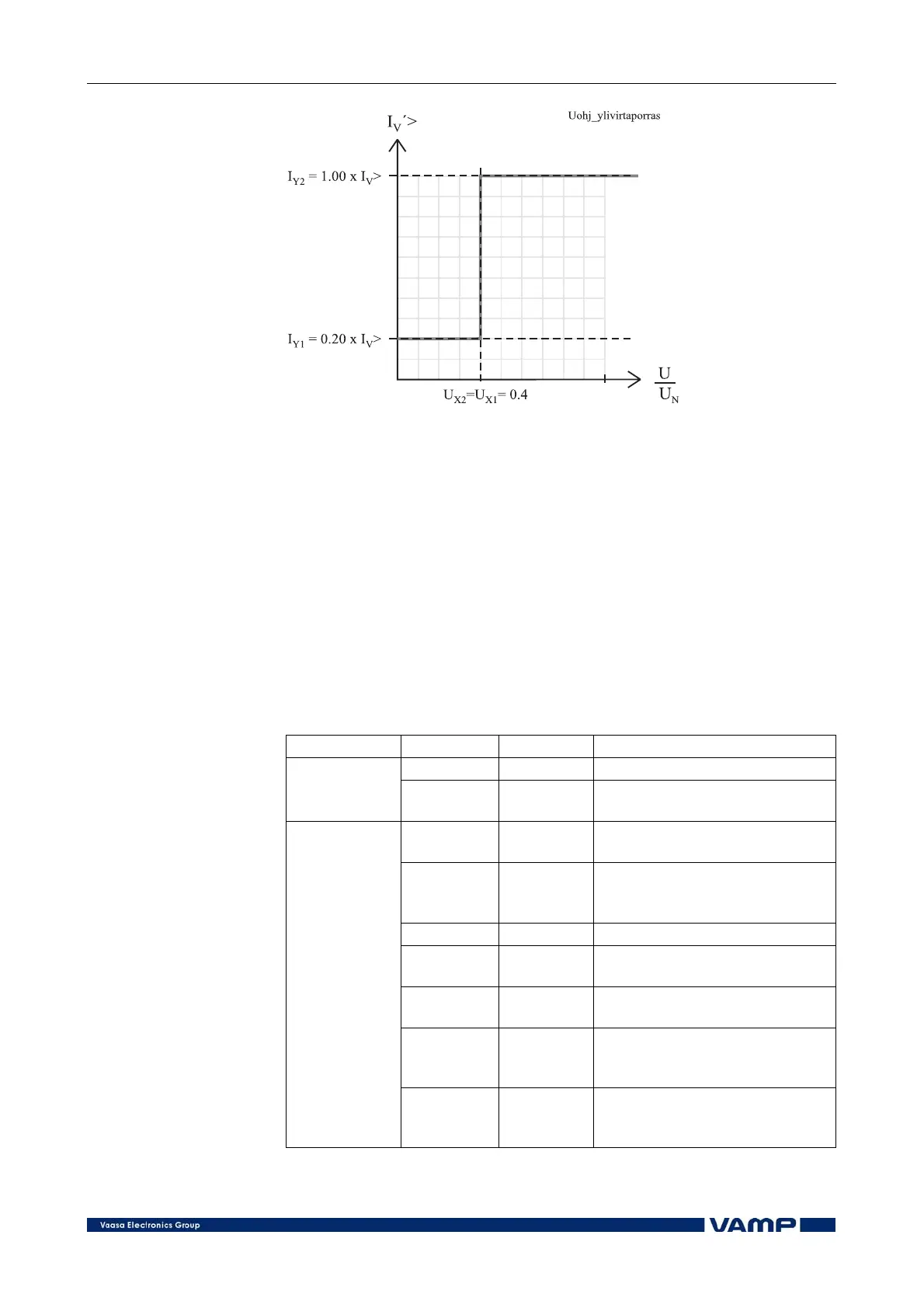
Figure 2.2.2-2 Voltage controlled overcurrent characteristics.
The voltage setting parameters U
X1
and U
X2
are proportional to
the rated voltage of the generator. They define the voltage
limits, within which the start current of the overcurrent unit is
restrained. The multipliers I
Y1
and I
Y2
are used for setting the
area of change of the start level of the overcurrent function in
proportion to the U
X1
and U
X2
settings.
The voltage restrained/controlled overcurrent stage operates
with definite time characteristic. The start current I
V
> and the
operating time t> can be set by the user.
Parameters of the voltage restrained and voltage controlled
overcurrent stage:
I
V
> (50/51V)
Parameter: Value/unit:
ILmax A Corresponding primary value
Measured
value
U1 %
Positive phase sequence voltage
as compared to Ugn
I
V
> A
Setting value in primary
current units
I
V
> xIn
Setting value as compared to
the generator rated current Ign
= Sgn/(Ugn x √3)
t> s Operating time
X1 %
Final value of voltage control =
X1% x U1
X2 %
Final value of voltage control =
X2% x U1
Y1 %I
V
>
Current start value = Y1% x
Iv> proportional to the voltage
X1
Setting
values
Y2 %I
V
>
Current start value = Y2% x
Iv> proportional to the voltage
X2