VAMP 210 Generator protection relay
Technical description
VAMP Ltd
22
Vamp 24h support phone: +358 (0)20 753 3264 VM210.EN004
Parameters of the residual voltage protection:
U
0
>, U
0
>> (59N)
Parameter: Value/unit:
Measured
value
U
0
% Residual voltage U
0
U
0
>, U
0
>> % Setting value U
0
> Setting
values
t>, t>> s Operating time
SCntr NA Cumulative start counter
TCntr NA Cumulative trip counter
Flt % Max. fault value
Recorded
values
EDly %
Elapsed time as compared to the
set operating time, 100% =
tripping
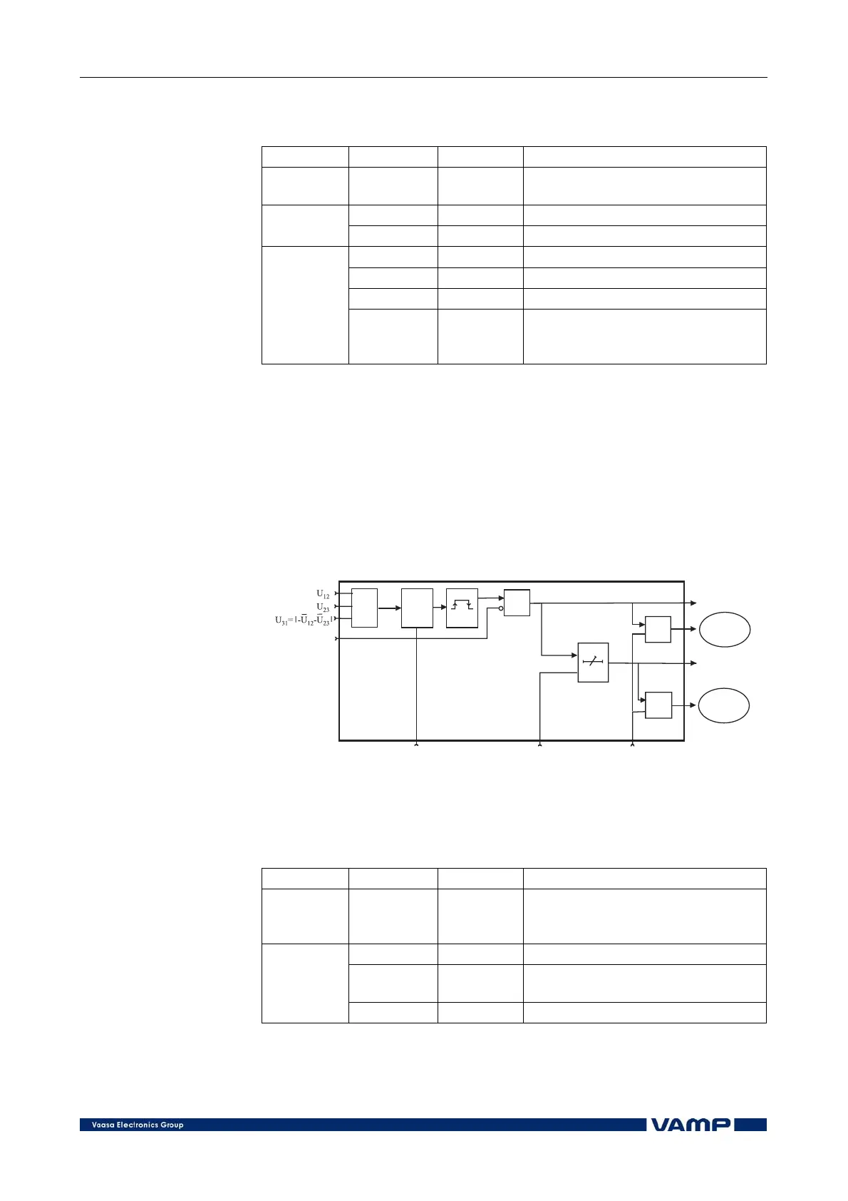
2.2.7. Overvoltage protection (59)
The three-phase overvoltage protection comprises two stages,
U> and U>>, with separately adjustable operating times.
The function is based on measuring the fundamental frequency
component of the phase-to-phase voltages, of which the highest
value constantly is compared with the set start value of the
overvoltage protection.
&
t
&
&
ylijsuoja2
MAX
t
s
t
r
>
Start
Trip
Register
event
Register
event
Block
Setting U>s Delay Enable events
Figure 2.2.7-1 Block diagram of the overvoltage protection.
Parameters of the overvoltage protection:
U>, U>> (59)
Parameter: Value/unit:
Measured
value
U
nMax
V
Maximum values of the primary
values of the phase-to-phase
voltages
U>, U>> % Setting value U
0
>
U>, U>> _ %Ugn
Setting value as compared to
generator rated voltage Ugn
Setting
values
t>, t>> s Operating time