VAMP 210 Generator protection relay
Technical description
VAMP Ltd
24
Vamp 24h support phone: +358 (0)20 753 3264 VM210.EN004
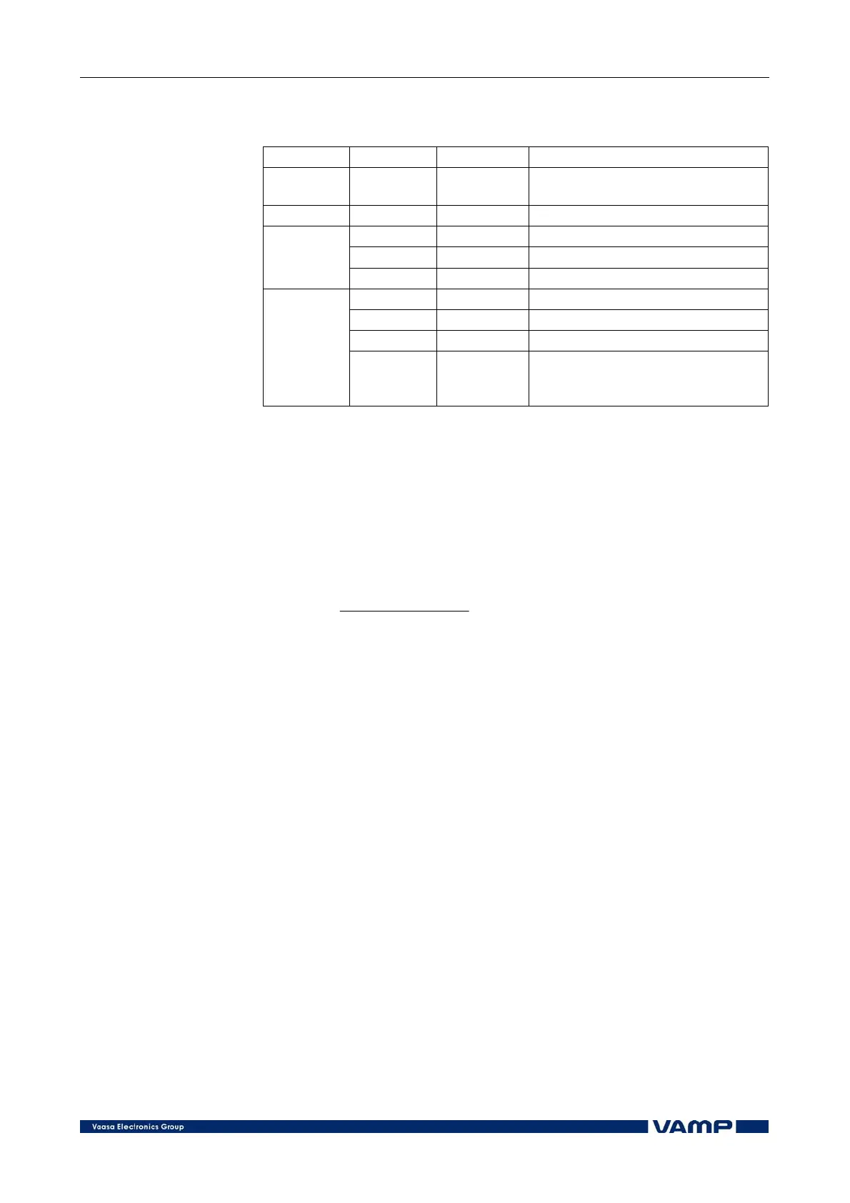
Parameters of the under voltage protection:
U
1
<, U
1
<< (27/60)
Parameter: Value/unit:
Measured
value
U
1
V Average main voltage
Display U
1
<, U
1
<< V Setting value
U
1
<, U
1
<< V Setting value
t>, t>> s Operating time [s]
Setting
values
NoComp % Block limit U<
SCntr Cumulative start counter
TCntr Cumulative trip counter
Flt % Fault voltage
Recorded
values
EDly %
Elapsed time as compared to the
set operating time, 100% =
tripping
2.2.9. Overload protection (49)
The overload function protects the stator winding against
thermal overload. The thermal stress of the stator can be
supervised by means of a thermal image, which can be
calculated from the standard heating expression according to
IEC 60255-8:
22
2
2
)(
ln
gen
p
IkI
II
t
⋅−
−
⋅=
τ
where:
τ = time to trip
I = generator heating and cooling time constant
ln = natural logarithm
Ip = preload current (corresponds to the heating
level reached)
k = factor for allowed continuous overload
I
GN
= generator rated current
The heating time constant (τ) and the load current factor (k)
corresponding to the maximum thermal load are adjustable.
The cooling time constant of the thermal overload protection is
the same as the heating time constant.
The thermal overload stage is provided with a separately
adjustable alarm function, the setting range of which is
60...100% of the thermal trip level.