VAMP 210 Generator protection relay
Technical description
VAMP Ltd
16
Vamp 24h support phone: +358 (0)20 753 3264 VM210.EN004
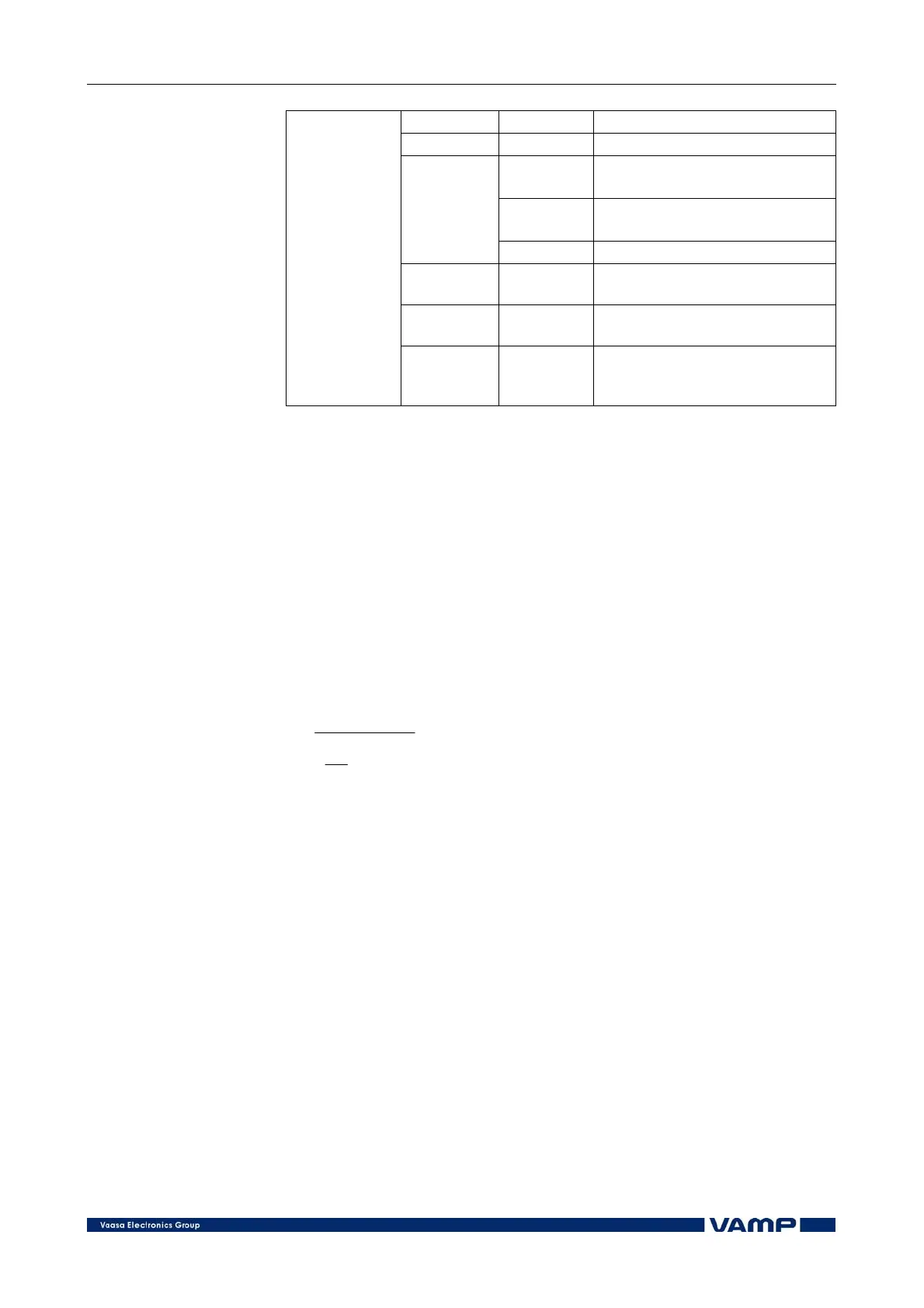
SCntr Cumulative start counter
TCntr Cumulative trip counter
1-N, 2-N,
3-N
Fault type/single-phase fault
e.g.: 1-N = fault on phase L1
1-2, 2-3,
1-3
Fault type/two-phase fault e.g.:
2-3 = fault between L2 and L3
Type
1-2-3 Fault type/three-phase fault
Flt xIn
Max. value of fault current as
compared to In
Load A
1 s mean value of pre-fault
phase currents IL1…IL3
Recorded
values
EDly %
Elapsed time as compared to
the set operating time, 100% =
tripping
2.2.3. Unbalance protection (46)
The purpose of the unbalanced load protection is to detect
unbalanced load conditions of the generator and to prevent the
generator rotor from excess heat caused by the unbalance. The
operation of the unbalanced load function is based on the
negative phase sequence current I
2
, which is calculated from
the phase currents using the method of symmetrical
components.
The negative phase sequence current is used for the calculation
of the operating time of the function according to the following
expression:
2
2
2
2
1
K
I
I
K
t
N
−
⎟
⎟
⎠
⎞
⎜
⎜
⎝
⎛
=
where:
t = operating time [s]
I
2
= negative phase sequence current
I
N
= generator rated current
K
1
= generator constant (I
2
2
t value) [s]
K
2
= maximum permitted continuous negative
phase sequence current of the generator
The operating time of the unbalanced load unit depends on the
magnitude of the negative phase sequence current, i.e. the
greater the unbalance the shorter the operating time. Figure
2.2.3-1 shows the characteristic curve of the unbalanced load
unit.