VAMP Ltd Generator protection relay
Technical description
VAMP 210
VM210.EN004 Vamp 24h support phone: +358 (0)20 753 3264
47
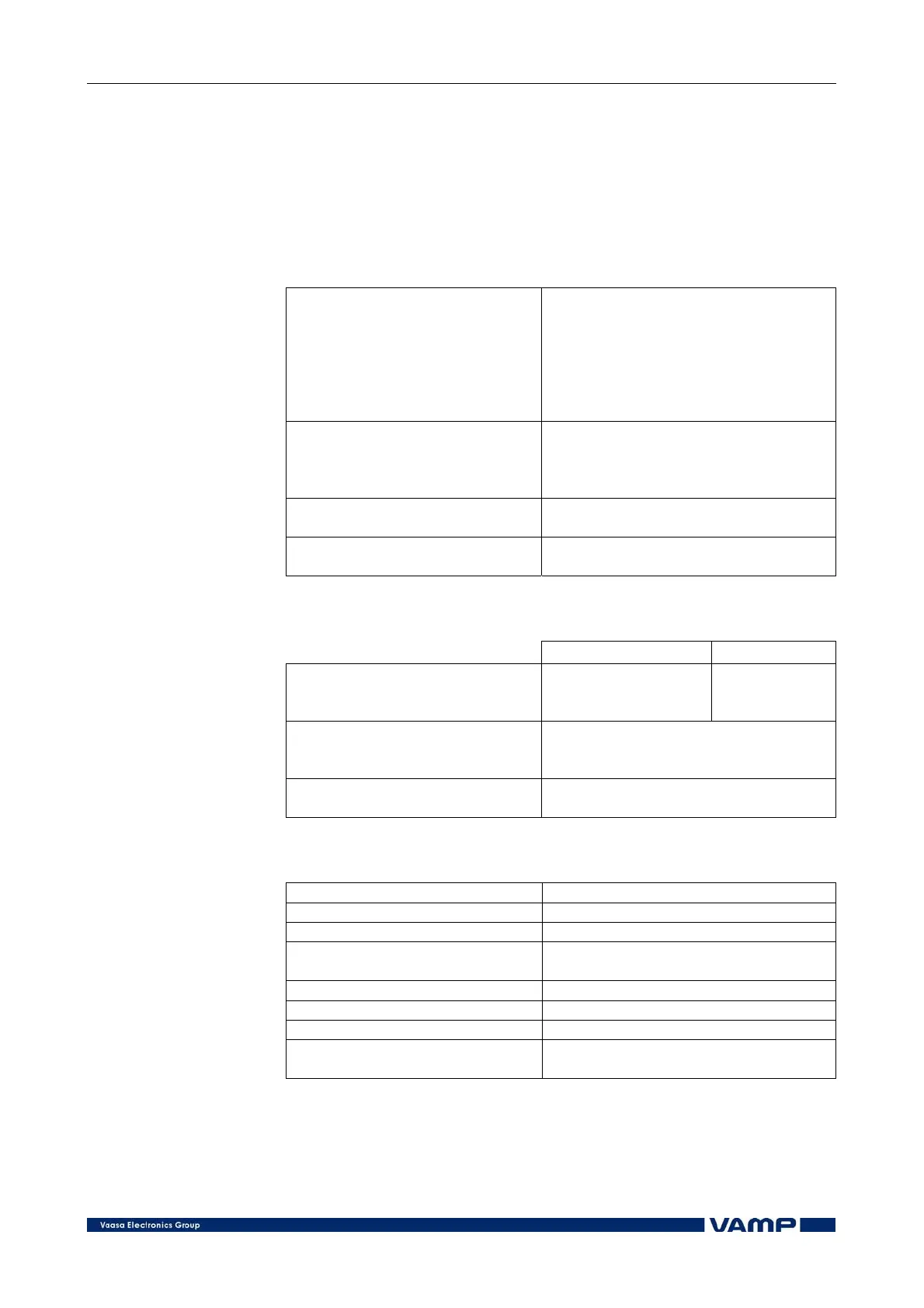
5. Technical data
5.1. Connections
5.1.1. Measuring circuitry
Rated current In 1 A or 5 A
- Current measuring range 0 - 50 x In
- Thermal withstand 4 x In (continuously)
20 x In (for 10 s)
100 x In (for 1 s)
- Burden < 0.1 VA (In = 1 A)
< 0.2 VA (In = 5 A)
Rated voltage Un 50 - 120 V (configurable)
- Voltage measuring range 0 - 175 V (100 V/110 V)
- Continuous voltage withstand 250 V
- Burden < 0.5V A
Rated frequency fn 45 - 65 Hz
- Frequency measuring range 16 - 75 Hz
Terminal block: Max. wire dimension:
- Solid or stranded wire 4 mm
2
(10-12 AWG)
5.1.2. Auxiliary voltage
Type A (standard) Type B (option)
Rated voltage Uaux 40 - 265 V ac/dc 18...36 V dc
110/120/220/240 V ac 24 V dc
48/60/110/125/220 V dc
Power consumption < 7 W (normal conditions)
< 15 W (output relays activated)
Max. permitted interruption time < 50 ms (110 V dc)
Terminal block: Max. wire dimension:
- Phoenix MVSTBW or equivalent 2.5 mm
2
(13-14 AWG)
5.1.3. Digital inputs
Number of inputs 6
Operation time 0.00 – 60.00 s (step 0.01 s)
Polarity NO (normal open) or NC (normal closed)
Inaccuracy:
- Operate time ±1% or ±10 ms
Internal operating voltage 48 V dc
Current drain when active (max.) Approx. 20 mA
Current drain, average value < 1 mA
Terminal block: Max. wire dimension:
- Phoenix MVSTBW or equivalent 2.5 mm
2
(13-14 AWG)