VAMP Ltd Generator protection relay
Technical description
VAMP 210
VM210.EN004 Vamp 24h support phone: +358 (0)20 753 3264
43
4. Connections
1
2
3
4
5
6
7
8
9
10
11
12
13
14
15
16
17
18
1
2
3
4
5
6
7
8
9
10
11
12
13
14
15
16
17
18
X3
X5
X1
VYX060A
40..265V
AC/DC
LOCAL
(RS-232)
REMOTE
(TTL)
1
3
5
7
9
11
13
15
17
19
2
4
6
8
10
12
14
16
18
20
X4
X6
X2
1
2
3
4
5
6
7
I
L1
I
L2
I
L3
I
0
I
0
I
L1
I
L2
I
L3
I
02
I
02
U
12
U
23
U
12
U
23
U
0
U
0
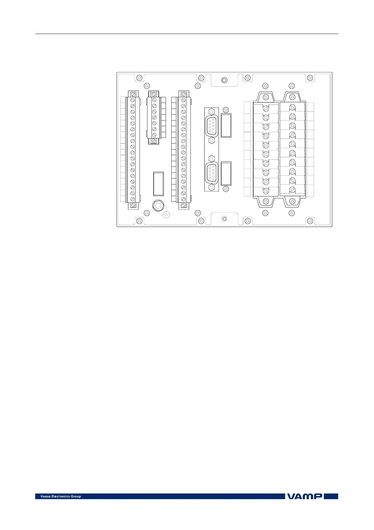
Figure 4-1 Connections on the rear panel of the relay.
The generator protection relay is connected to the protected
object through the following measuring and control
connections, see Figure 4-1:
• Phase currents I
L1
, I
L2
and I
L3
(terminals X1: 1-6)
• Residual currents I
01
and I
02
(terminals X1: 7-10)
• Phase-to-phase voltages U
12
and U
23
(terminals X1: 11-
14)
• Residual voltage U
0
(terminals X1: 17-18)
4.1. Digital inputs
Further the generator protection relay can collect status
information and alarm signals via six digital inputs (terminals
X3: 2-7).
The digital inputs can be used to:
• Block protection stages under certain conditions.
• Get time stamped event code from any auxiliary
contact.
• Control the output relays.
• Supervise the trip circuit.
The digital uses the internal 48 V dc auxiliary voltage of the
relay (terminal X3: 1). Potential-free contacts must be available
in the protected object for transfer of status information to the
relay.