VAMP 210 Generator protection relay
Technical description
VAMP Ltd
40
Vamp 24h support phone: +358 (0)20 753 3264 VM210.EN004
3.3. Generator-transformer unit
L1
L2
L3
L1 L2 L3
A
B
A
B
a
a
b
b
L1
L2
L3
A
B
C
a
b
c
G
~
U<
U<<
U>
U>>
X<
X<<
f>
f<
f<<
I,U>
0
0
I,U>>
0
0
P>
P>>
I>
0
I>>
0
3I>
3I>>
I>
2
F>
X3
2
3
4
5
6
7
1
2
18
1
17
3
4
5
6
7
8
9
10
11
12
13
14
17
18
X1
X3
X4
X5
IL1
IL2
IL3
I
01
I
02
U
12
U
23
U
0
12
13
14
15
9
11
10
10
11
12
13
16
14
17
15
18
X3
A1
T2
T1
A5
A4
A3
A2
IF
X2
5
6
7
8
Blocking and
output matrix
+48VDC
Digital
inputs
Protection function
VAMP 210
vamp210appl_3
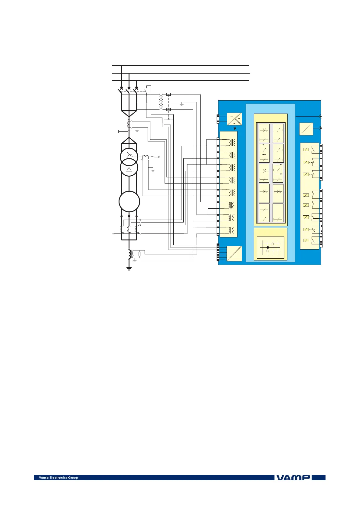
Figure 3.3-1 Generator-transformer unit
Besides the typical generator protection functions the VPG 210
relay includes the transformer earth-fault protection. Whatever
phase difference and voltage ratio of the transformer can be
compensated in the relay in case VTs and CTs are on different
sides of the unit transformer.
The earth-fault protection of the transformer is based on an
OR-function between the current inputs I
01
and I
02
.
The stator earth-fault protection (reach 95%) is based on
measuring the fundamental frequency component of the
residual voltage U
0
with the overvoltage stage (59GN).
Via the digital inputs of the relay various signals can be
transferred into the relay, such as information about the
operation of a MCB in the measuring circuit or circuit-breaker
status information.