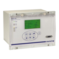
VAMP 210 Generator protection relay
Technical description
VAMP Ltd
44
Vamp 24h support phone: +358 (0)20 753 3264 VM210.EN004
4.2. Auxiliary voltage
The external auxiliary voltage Uaux (standard 40…265 V ac or
dc) for the relay is connected to the terminals X3: 17-18.
Note!
Polarity of the auxiliary voltage Uaux (24 V dc, option B):
- = X3:17 and + = X3:18.
4.3. Output relays
The generator protection relay is equipped with seven
configurable output relays and a separate output relay for the
self-supervision system, see Figure 4-1:
• Trip relays T1 and T2 (terminals X3: 12-13 and 14-15)
• Alarm relays A1 - A5 (terminals X2: 5-6, 7-8, 10-12, 13-15
and X3: 9-11)
• Self-supervision system output relay IF (terminals X2: 16-
18)
4.4. Serial communication connection
• RS 232 serial communication connection for computers,
connector LOCAL (RS 232), connectors on front panel and
rear panel connected in parallel, see Figure 4-1.
• Remote control connection, connector REMOTE (TTL) on
the rear panel of the relay, see Figure 4-1.
4.5. Arc Protection
The optional arc protection card includes two arc sensor
channels. The arc sensors are connected to terminals X6: 4-5
and 6-7.
The arc information can be transmitted and/or received
through the digital input and output channels. This is a 48 Vdc
signal.
Connections:
X6: 1 Digital input (BI)
X6: 2 Digital output (BO)
X6: 3 GND
X6: 4-5 Sensor 1
X6: 6-7 Sensor 2

 Loading...