VAMP Ltd Generator protection relay
Technical description
VAMP 210
VM210.EN004 Vamp 24h support phone: +358 (0)20 753 3264
33
Apparent power S
Measuring range
0... ±2 x S
N
(S
N
= I
N
* U
N
* √3)
Active power P
Measuring range 0... ±2 x S
N
Reactive power Q
Measuring range 0... ±2 x S
N
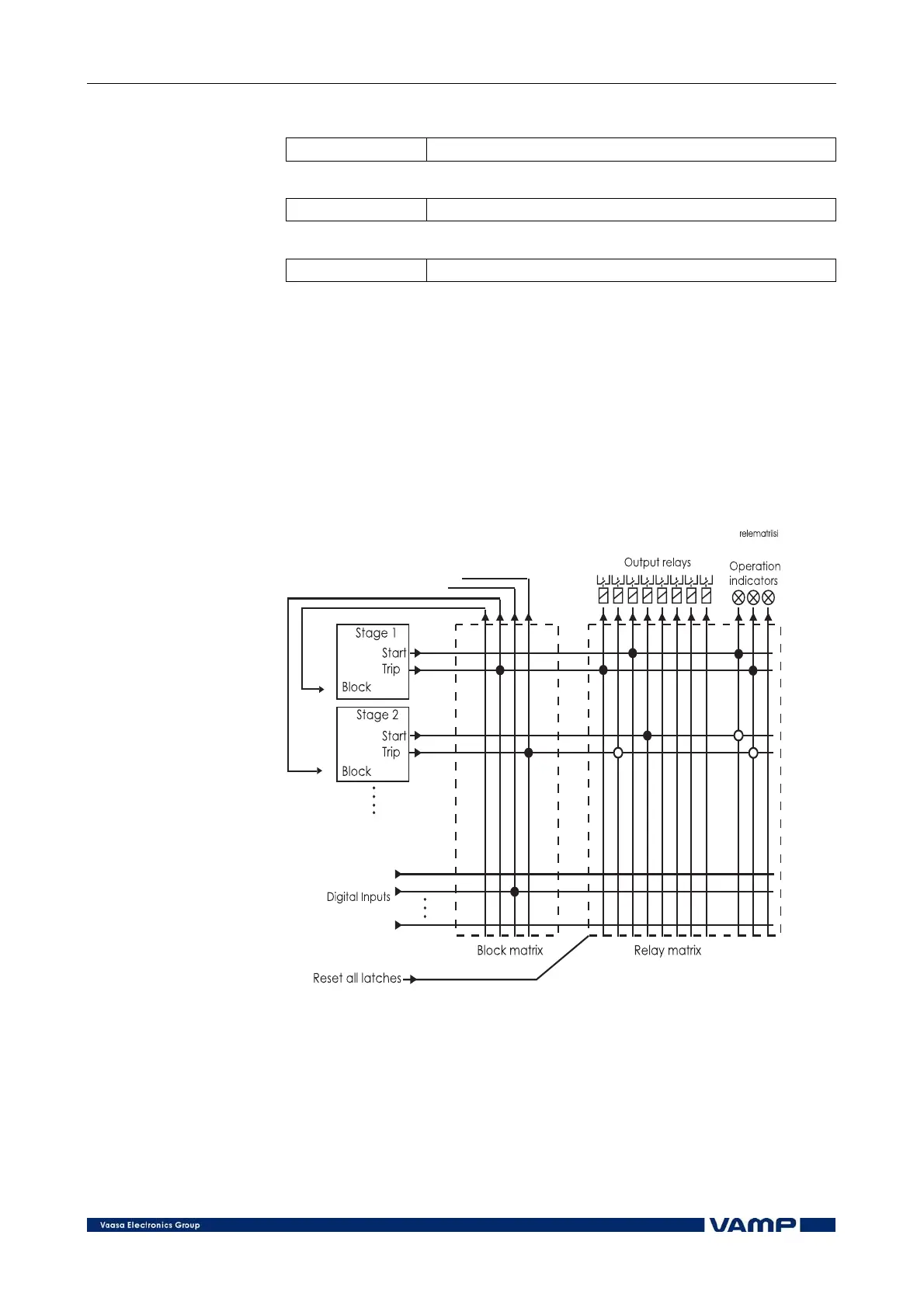
2.4. Output relay and blocking functions
In the generator protection relay VAMP 210 all start and trip
signals of the protection stages can be freely routed to the
output relays and operation indicators according to the
requirements of the application. The functions can also be
blocked and for this purpose both internal relay signals and
external control signals can be used. Figure 2.4-1 shows the
operating principle of the grouping and blocking matrices.
Figure 2.4-1 Operating principle of the grouping and blocking matrices.