VAMP 210 Generator protection relay
Technical description
VAMP Ltd
36
Vamp 24h support phone: +358 (0)20 753 3264 VM210.EN004
Available links
The following channels can be linked to Disturbance Recorder:
• IL1, IL2, IL3, IL, Io, Io2, I2/I1
• U12, U23, U31, UL1, UL2, UL3
• U1, U2/U1, Uo
• Uphase, Uline
• f
• P, Q, S, PF
• cosϕ
• DI, DO
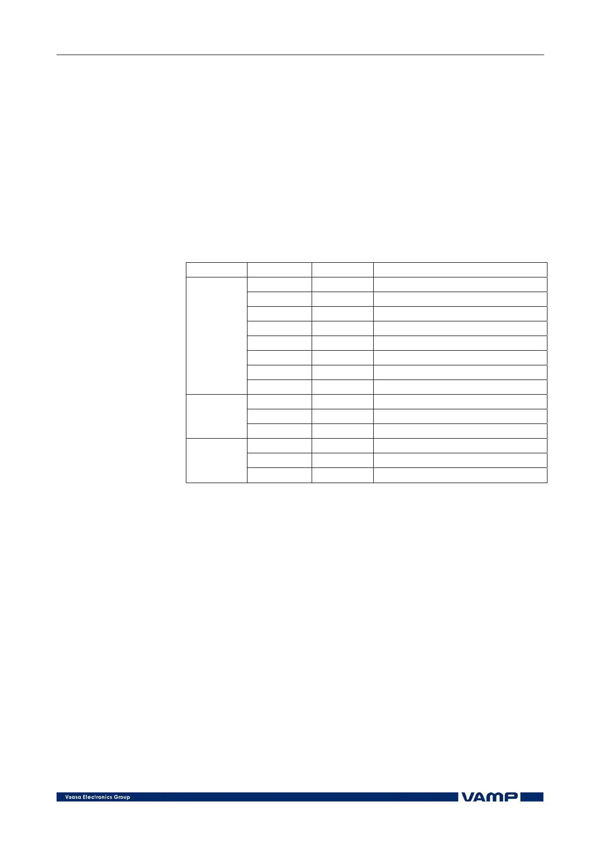
Parameters of the Disturbance Recorder
Parameter: Value/unit:
Mode Mode of the recording
Rate Sample rate
Time s Recording time
PreTrig % Pre-trigger time
MnlTrig Manual trig
Size Size of one recording
MAX time s Maximum time of recordings
Setting
values
MAX size Maximum size of recordings
Links Connected links
AddLink Add links
Recorder
links
ClrLnks Clear links
Status Status of the recorder
Time status % Status of the pre-triggering
Recorded
values
ReadyRec Number of ready records
2.7. Self-supervision
The functions of the micro controller and the associated
circuitry as well as the program execution are supervised by
means of a separate watchdog circuit. Besides supervising the
relay the watchdog circuit attempts to restart the micro
controller in a fault situation. If the restarting fails the
watchdog issues a self-supervision alarm because of a
permanent relay fault.
When the watchdog circuit detects a permanent fault it always
blocks any control of the other output relays, except for the self-
supervision output relay.
Also the internal supply voltage is supervised. Should the
auxiliary supply of the relay disappear, an IF alarm is
automatically given, because the IF output relay is normally
always energized when the auxiliary supply is on and within
the permitted range.