VAMP 210 Generator protection relay
Technical description
VAMP Ltd
38
Vamp 24h support phone: +358 (0)20 753 3264 VM210.EN004
3.1. Directly connected generator
L1
L2
L3
L1 L2 L3
G
~
U<
U<<
U>
U>>
X<
X<<
f>
f<
f<<
I,U>
0
0
I,U>>
0
0
P>
P>>
I>
0
I>>
0
3I>
3I>>
I>
2
F>
X3
2
3
4
5
6
7
1
2
18
1
17
3
4
5
6
7
8
9
10
11
12
13
14
17
18
X1
X3
X4
X5
IL1
IL2
IL3
I
01
I
02
U
12
U
23
U
0
12
13
14
15
9
11
10
10
11
12
13
16
14
17
15
18
X3
X2
5
6
7
8
A1
T2
T1
A5
A4
A3
A2
IF
230V~
VEO-MSV
+48VDC
Digital
inputs
Blocking and
output matrix
Protection function
VAMP 210
vamp210appl_1
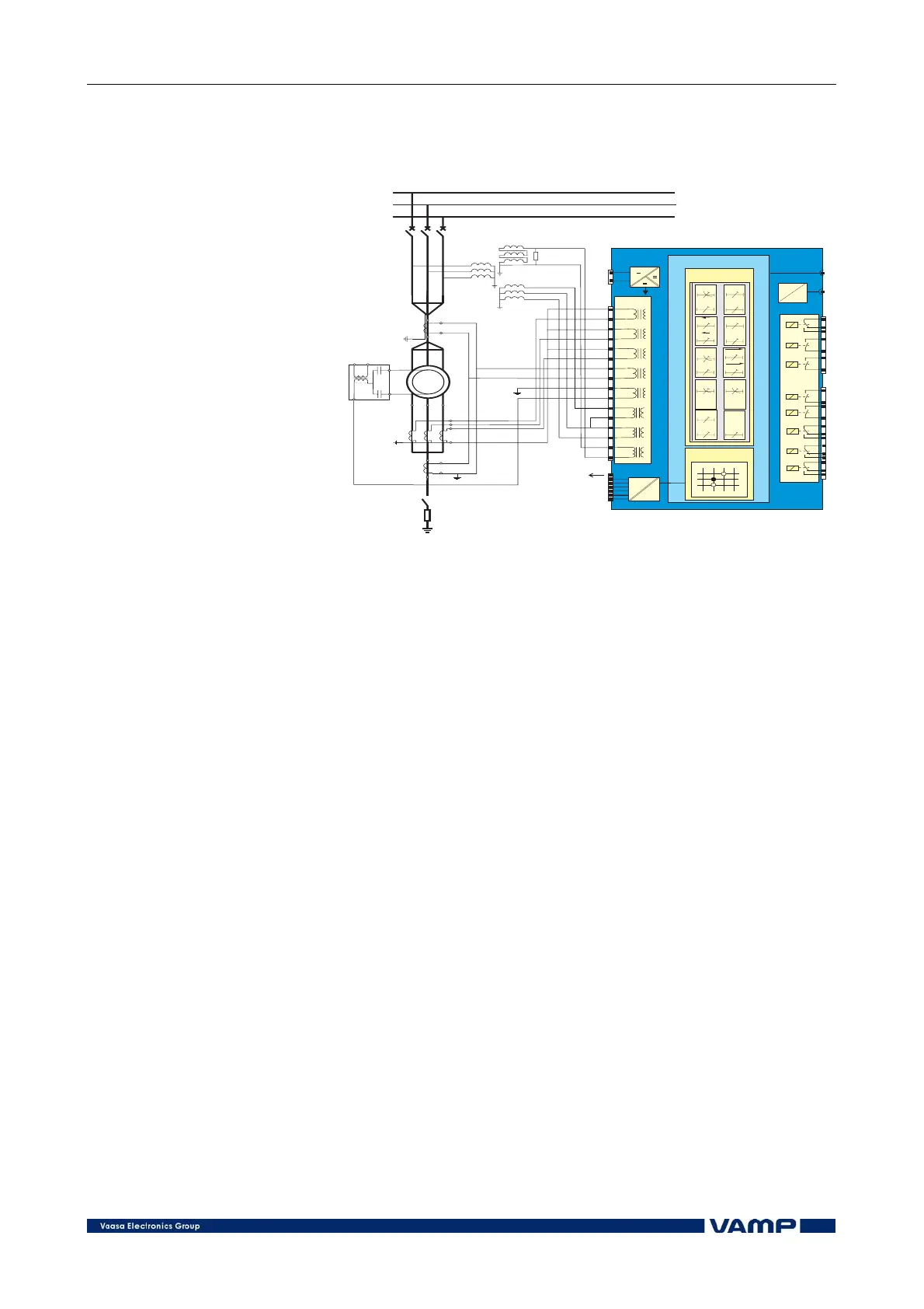
Figure 3.1-1 Generator connected directly to the distribution busbar.
Earthed generator neutral.
The generator protection relay VPG 210 is suitable for use in
directly earthed and high/low resistance earthed systems. The
differential and directional earth-fault protection provides a
sensitive and selective protection solution in high resistance
earthed systems.
In directly earthed or low resistance earthed systems the non-
directional earth-fault stage constitutes a sufficiently selective
earth-fault protection when energized from two current
transformers forming a differential current connection.
The rotor earth-fault protection can be realized with the non-
directional earth-fault stage using the energizing current input
I
02
in combination with a current injection device, e.g. type
VEO-MSV.