VAMP Ltd Generator protection relay
Operation and configuration
VAMP 210
VM210.EN004 Vamp 24h support phone: +358 (0)20 753 3264
7
2. User interface
2.1. General
The VAMP 210 protection relay can be controlled in three
ways:
• Locally with the push-buttons on the relay front panel
• Locally using a PC connected to the serial port on the front
panel or on the rear panel of the relay (both cannot be used
simultaneously)
• Via the remote control port on the relay rear panel.
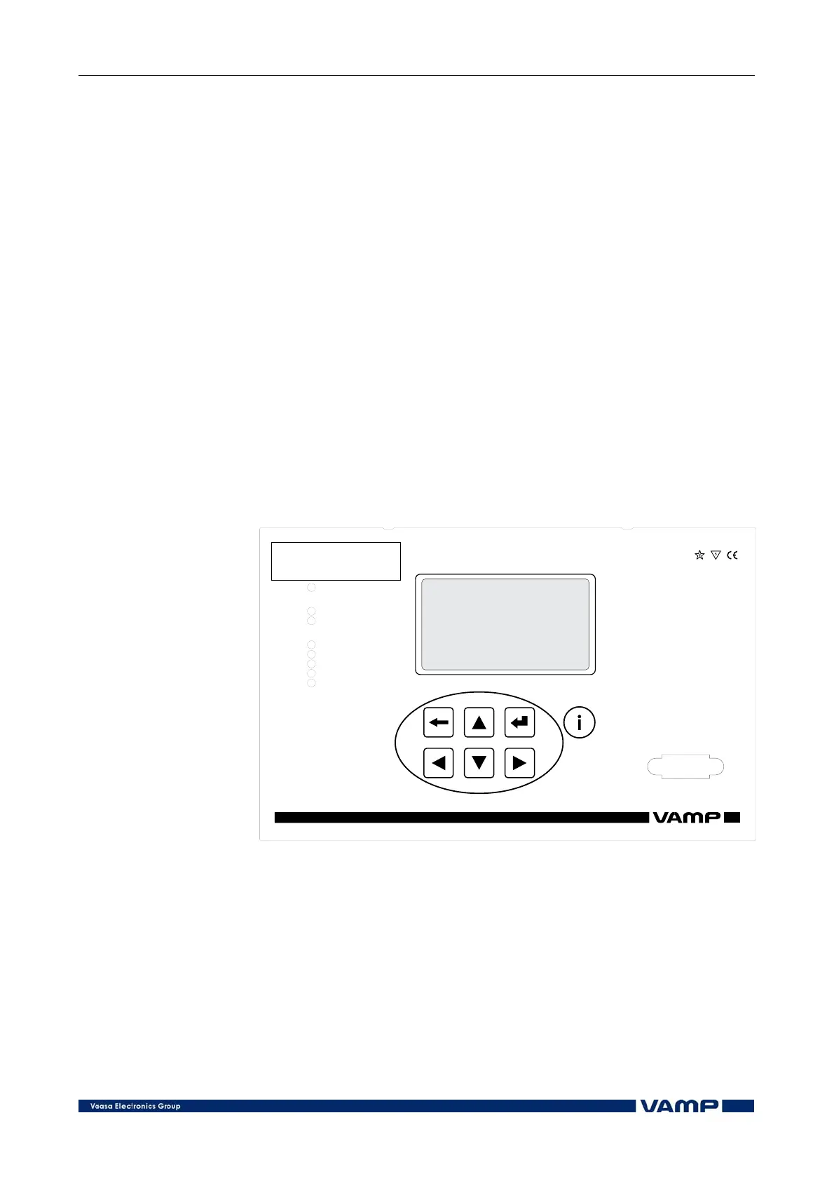
2.2. Relay front panel
The figure below shows the front panel of the relay and the
location of the user interface elements used for local control.
VY 062 B
Power
Error
Com
Alarm
Trip
A
B
C
1
3
2
4
VAMP 210
Generator Protection Relay
Figure 2.2-1 Relay front panel.
1. LCD dot matrix display
2. Key pad
3. LED indicators
4. RS 232 serial communication port for PC