2.14 Overvoltage protection U> (59)
VAMP 24h support phone +358 (0)20 753 3264
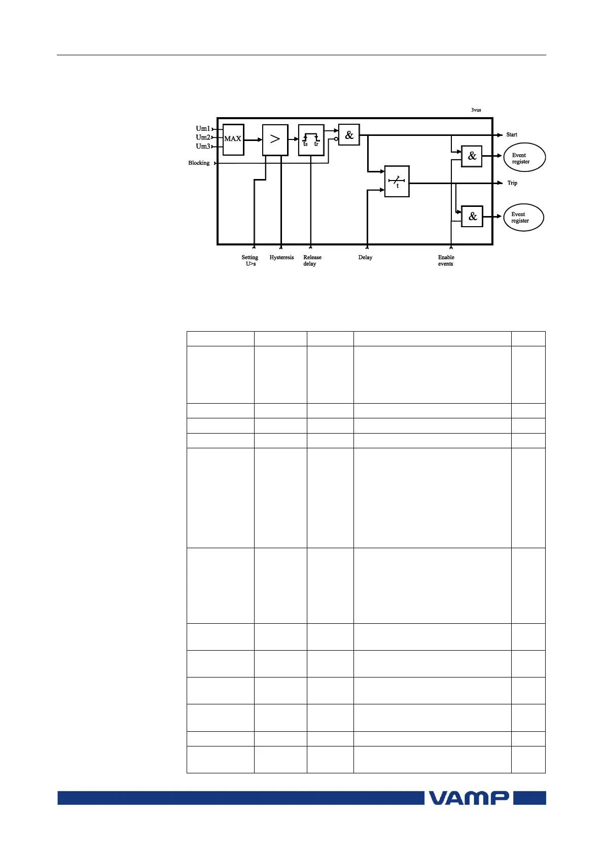
Figure 2.14-1 shows the functional block diagram of the
overvoltage function stages U>, U>> and U>>>.
Figure 2.14-1 Block diagram of the three-phase overvoltage stages U>, U>>
and U>>>.
Parameters of the overvoltage stages U>, U>>, U>>> (59)
Current status of the stage
Digital signal to select the
active setting group
None
Digital input
Virtual input
LED indicator signal
Virtual output
Force flag for status forcing for
test purposes. This is a
common flag for all stages and
output relays, too.
Automatically reset by a 5-
minute timeout.
The supervised value. Max. of
U
L12
, U
L23
and U
L31
Pick-up value scaled to
primary value
Pick-up setting relative to U
N
Release delay (U> stage only)
Dead band size i.e. hysteresis