7.4 Trip circuit supervision
VAMP 24h support phone +358 (0)20 753 3264
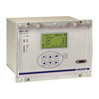
Figure 7.4.2-6 An example of digital input DI1 configuration for trip circuit
supervision with one wet digital input.
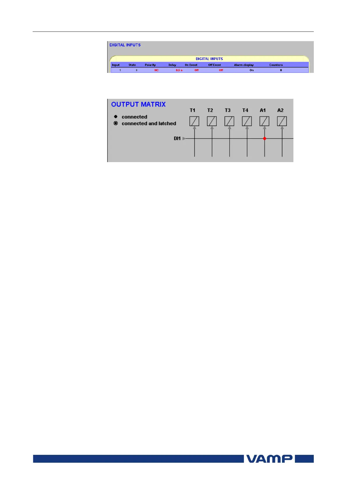
Figure 7.4.2-7 An example of output matrix configuration for trip circuit
supervision with one wet digital input.
Example of dimensioning the external resistor R:
110 Vdc –5 % + 10%
Auxiliary voltage with tolerance. Short time voltage
dips more than 5 % are not critical from the trip
circuit supervision point of view.
Relay type for the K1 auxiliary relay:
Phoenix Contact 2941455
EMG 17-REL/KSR-120/21-21-LC Au
120 Vac/dc –20 % + 10%
Coil voltage of the auxiliary relay K1
6 mA
Nominal coil current of the auxiliary relay K1
50 W
Rated power of the open coil of the circuit breaker.