7.4 Trip circuit supervision
VAMP 24h support phone +358 (0)20 753 3264
Equation 7.4.2-3
P = 121^2/22000 = 0.67 W
A 0.5 W resistor will be enough for this short time peak power,
too. However, if the trip relay is closed for longer time than a
few seconds, a 1 W resistor should be used.
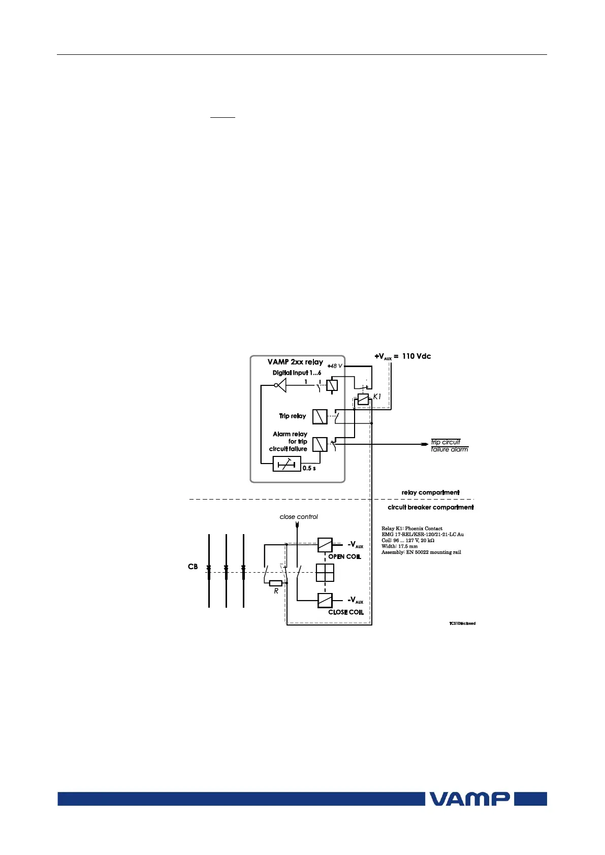
Using any of the non-dry digital inputs DI1...DI6
In this scheme an auxiliary relay is needed to connect the wet
digital input to the trip circuit (Figure 7.4.2-5). The rated coil
voltage of the auxiliary relay is selected according the rated
auxiliary voltage used in the trip circuit. The operating voltage
range of the relay should be as wide as possible to cover the
tolerance of the auxiliary voltage.
In this application using the other wet inputs for other
purposes is not limited unlike, when using the dry inputs.
Figure 7.4.2-5 Trip circuit supervision using one of the VAMP 200 series
internally wetted digital input (DI1...DI6) and auxiliary relay K1 and an
external resistor R. The circuit-breaker is in the closed position. The
supervised circuitry in this CB position is double-lined. The digital input is
in active state when the trip circuit is complete.