2.7 Directional overcurrent protection
Idir> (67)
VAMP 24h support phone +358 (0)20 753 3264
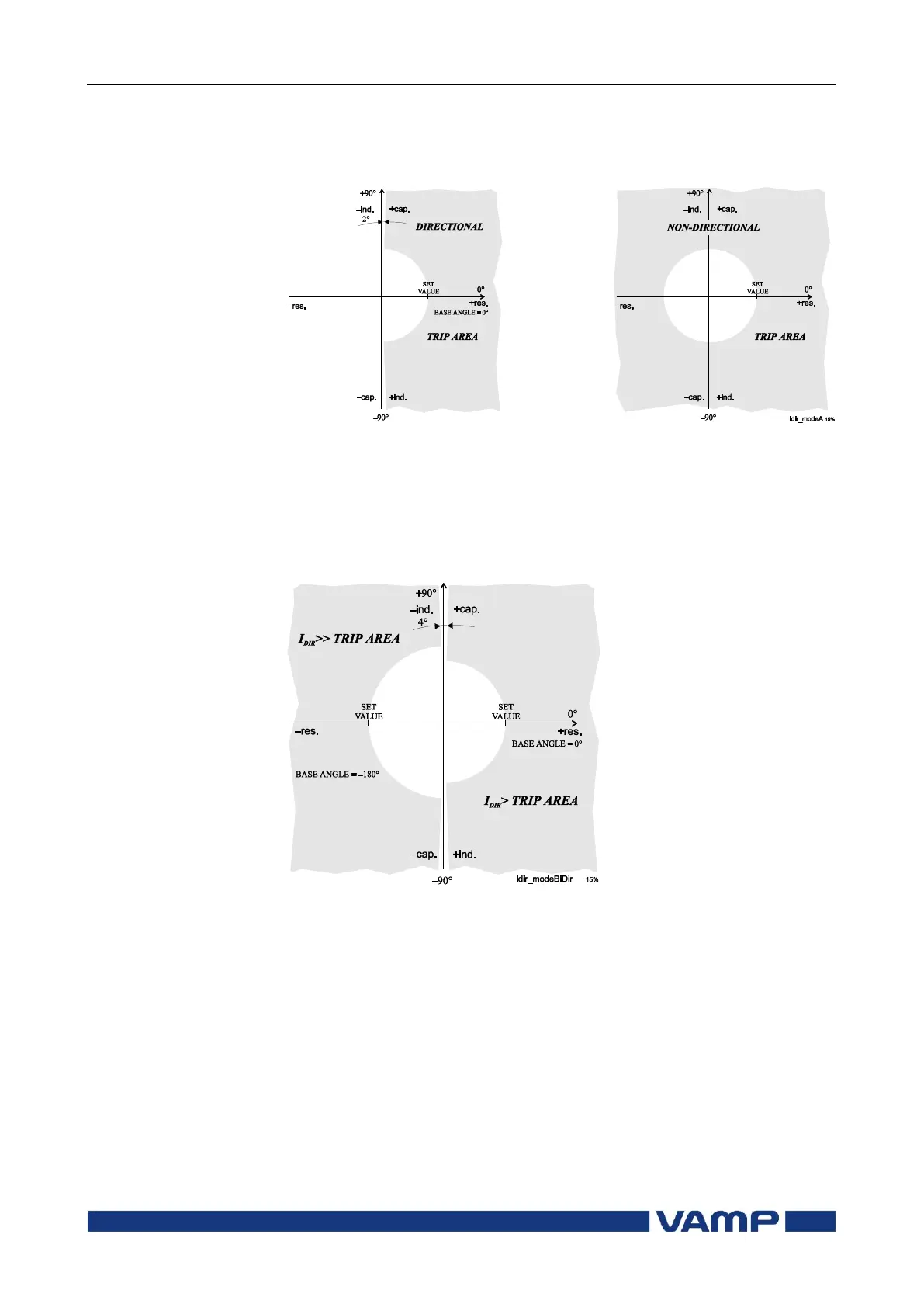
Two modes are available: directional and non-directional
(Figure 2.7-2). In the non-directional mode the stage is acting
just like an ordinary overcurrent 50/51 stage.
Figure 2.7-2.Difference between directional mode and non-directional mode.
The grey area is the trip region.
An example of bi-directional operation characteristic is shown
in Figure 2.7-3. The right side stage in this example is the
stage Idir> and the left side is Idir>>. The base angle setting of
the Idir> is 0° and the base angle of Idir>> is set to –180°.
Figure 2.7-3. Bi-directional application with two stages Idir> and Idir>>.
When any of the three phase currents exceeds the setting value
and – in directional mode – the phase angle including the base
angle is within the active 88° wide sector, the stage picks up
and issues a start signal. If this fault situation remains on
longer than the delay setting, a trip signal is issued.
Four independent stages
There are four separately adjustable stages available: I
dir
>,
I
dir
>>, I
dir
>>> and I
dir
>>>>.