INSTALLATION Series
32/107
Edition 2017-11-24 813316EB
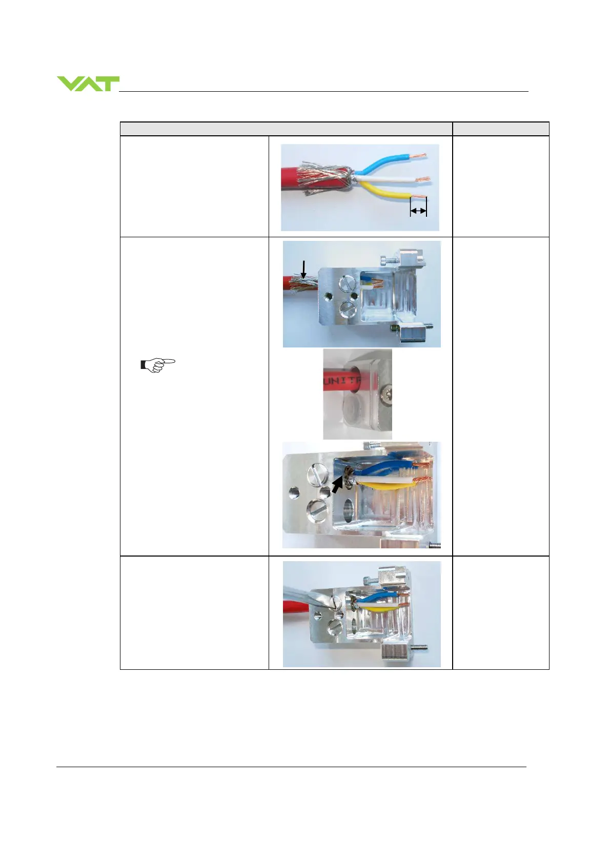
9. Remove the wire coat carefully
about 5mm
Wire strippers
10. Insert the cable(s) at
connector hosing as shown in
the pictures, see also chapter
CC-Link connector
If valve in CC-Link network is
at «first or last station» install
the CC-Link cable at position A
and close B with blind plug C.
If valve in CC-Link network at
«…stations…» install the CC-
Link cables at position A and
B.
11. Fasten the strain-relief screw
until the cable can not pulled
out by manual force
Screw driver
size 4
5mm
Shield
Pos. B
C
 Loading...


