Series 651 INSTALLATION
605451EC Edition 2014-07-10 19/
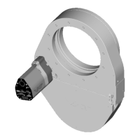
4.2.2 Connection overview
System:
1 Valve
2 Process chamber
3 Gas inlet
4 Pressure sensor(s)
5 Sensor cable(s)
6 Controller and actuator
7 Cable to remote control unit
8 Cable to power supply
9 Pump
Controller:
4.2.3 Installation procedure
1. Install valve [1] into the vacuum system. Valve seat side should face process chamber. The valve seat
side is indicated by the symbol "∇" on the valve flange.
M
3
4
5
7
8
2
1
9
6
• Do not tighten the flange screws stronger than indicated under «Tightening

 Loading...