INSTALLATION Series
22/99
Edition 2014-07-10 605451EC
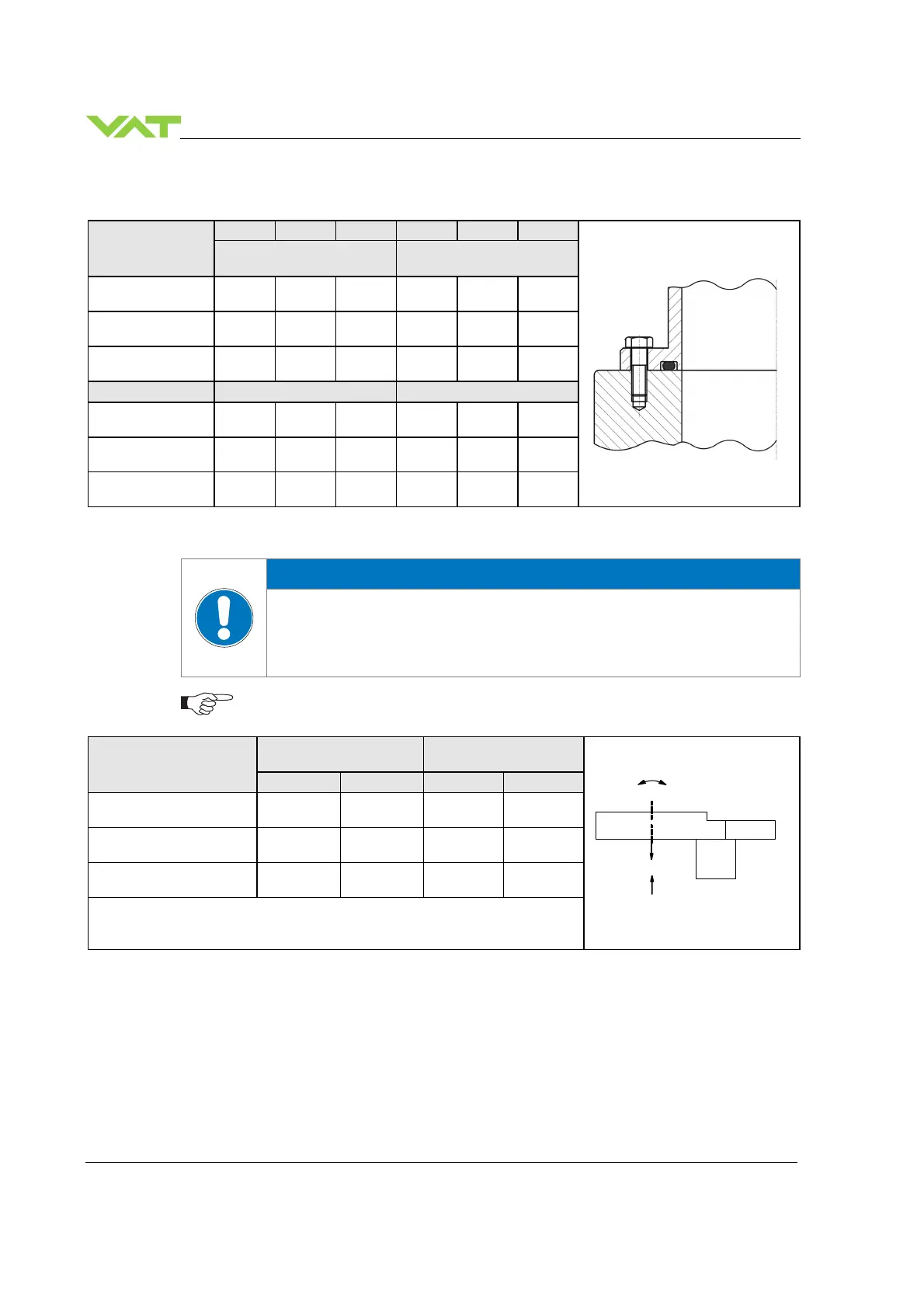
4.3.2 Mounting with O-ring in grooves
Valve size
ISO-F JIS ASA-LP
ISO-F JIS ASA-LP
max. tightening torque
(Nm)
max. tightening torque
(lbs . ft)
DN160 / 6“
(65144 - . . . . - . . . . )
35-40 35-40 35-40 26-30 26-30 26-30
DN200 / 8“
(65146 - . . . . - . . . . )
35-40 35-40 80-90 26-30 26-30 59-67
DN250 / 10“
(65148 - . . . . - . . . . )
35-40 65-70 80-90 26-30 48-52 59-67
hole depth (mm) hole depth (inch)
DN160 / 6“
(65144 - . . . . - . . . . )
14 14 14 0.55 0.55 0.55
DN200 / 8“
(65146 - . . . . - . . . . )
15 15 14 0.59 0.59 0.59
DN250 / 10“
(65148 - . . . . - . . . . )
16 16 16 0.63 0.63 0.63
4.3.3 Admissible forces
NOTICE
Force at valve body
Forces from evacuating the system, from the weight of other components, and from
baking can lead to deformation and malfunctioning of the valve.
Do not higher force the valve body as specified.
The following forces are admissible.
Valve size
Axial tensile or
compressive force «F
A
»
Bending moment «M»
N lb. Nm lbf.
DN160 / 6“
(65144 - . . . . - . . . . )
2000 440 80 60
DN200 / 8“
(65146 - . . . . - . . . . )
2000 440 80 60
DN250 / 10“
(65148 - . . . . - . . . . )
2500 550 100 75
For a combination of both forces (F
A
and M) the values are invalid.
Verify that the depth of the mounting screws is min. 1 x thread diameter.
Please contact VAT for more information.
F
A
M

 Loading...