Series 651 INSTALLATION
605451EC Edition 2014-07-10 37/
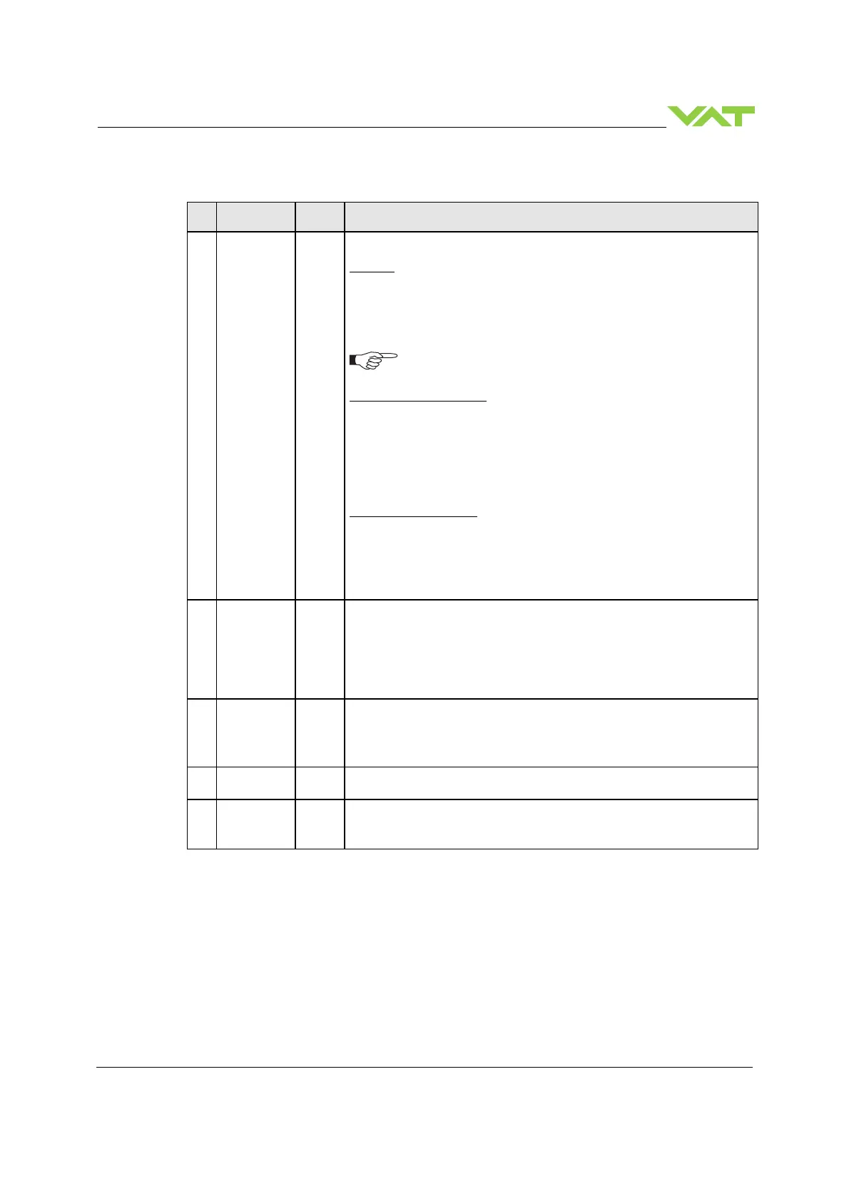
4.4.10 Analog inputs and outputs
25
SETPOINT
Analog
input
1)
The meaning of the setpoint input depends on the operation mode.
LEARN:
A voltage of 0-10V shall be applied to this input as pressure limit for
learn. The limit pressure is in linear relation to the applied voltage. 10V
relates to sensor full scale.
In case of 2 sensor operation 10V relates to sensor 1 full scale (high
To activate pressure limit function for remote operation it must
be configured accordingly. Refer to «Interface configuration»
PRESSURE CONTROL:
A voltage of 0-10V shall be applied to this input as pressure setpoint.
The pressure setpoint is in linear relation to the applied voltage.
Depending on selected SETPOINT RANGE 10V means either sensor full
scale or 10% of sensor full scale.
In case of 2 sensor operation 10V relates to sensor 1 full scale (high
range).
POSITION CONTROL:
A voltage of 0-10V shall be applied to this input as position setpoint. The
position setpoint is in linear relation to the applied voltage. 0V is closed
but not isolation function and 10V is open position.
(Use digital input for isolation function)
12
PRESSURE
Analog
output
1
)
This output indicates the current pressure as 0-10V. The output voltage
is in linear relation to the pressure. Depending on the selected
SETPOINT RANGE 10V means either sensor full scale or 10% of sensor
full scale.
In case of 2 sensor operation sensor full scale relates to sensor 1 (high
range).
11
POSITION
Analog
output
1
)
This output indicates the current valve position as 0-10V voltage range.
The voltage is in linear relation to the valve position. 0V is closed but not
isolation function and 10V is open position.
(Use digital output for isolation function)
13
ANALOG
Analog
Ground for analog input and analog outputs.
1
CHASSIS
GROUND
Chassi
s
ground
Chassis ground connected to case. Shall be used to connect cable
shield.
1) Refer to «Function and wiring» for details about input / output circuit.

 Loading...