OPERATION
Series
68/99
Edition 2014-07-10 605451EC
5.6.2 Operation
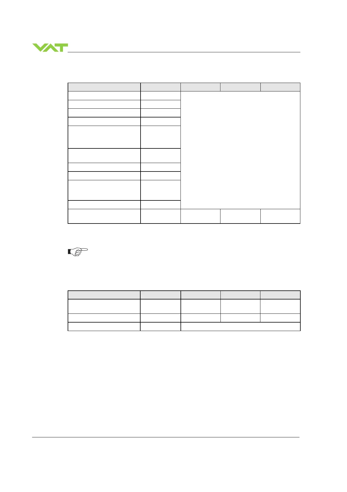
Description / Mode Digit 1 Digit 2 Digit 3 Digit 4
PRESSURE CONTROL mode
P
0…100
= valve position (%, 0 = closed / 100 = open)
POSITION CONTROL mode
V
Valve closed
C
Valve open
O
Closed / open interlock
(Valve closed / open
by digital input)
I
HOLD (position frozen)
activated
H
ZERO running
Z
LEARN running
L
Safety mode established.
Refer to «Safety mode» for
details.
D
Power failure
F
Service request
1)
(valve
requires cleaning)
S R
1)
If SR is blinking alternatively with the actual mode display (e.g. P.11 ⇔ ..SR) the valve requires
cleaning.
RxD / TxD activity of RS232 communication is displayed by 2 blinking dots in digit 2.
The lower dot indicates RxD activity where the upper dot indicates TxD activity. The
indication is not real time.
5.6.3 Errors
Description Digit 1 Digit 2 Digit 3 Digit 4
Compressed air failure
(< 4 bar / 55 psi)
A I R f
Compressed air on exhaust
A I R x
Fatal error occurred
E
Error code. Refer to «Trouble shooting» for details
5.6.4 Safety mode
By means of an external switch (see connection diagrams «Electrical connection») the motor power
supply can be interrupted. In this case the valve enters the ‘safety mode’. This motor interlock prevents
the valve from moving (e.g. maintenance work). Data reading from the control unit remains possible.
When motor interlock is active during power up the valve directly enters the ‘safety mode’ and is not able
to synchronize. Display shows ‘D C’ or ‘D999’. In this case synchronization cycle will be done when
motor interlock is deactivated. Then Display shows ‘INIT’ for a moment followed by ‘SYNC’.
When ‘safety mode’ is entered from operation (i.e. pressure control mode), the unit will automatically
switch to position control mode and remain at current position. Once motor interlock is deactivated the
unit remains in position control mode.

 Loading...