INSTALLATION Series
30/99
Edition 2014-07-10 605451EC
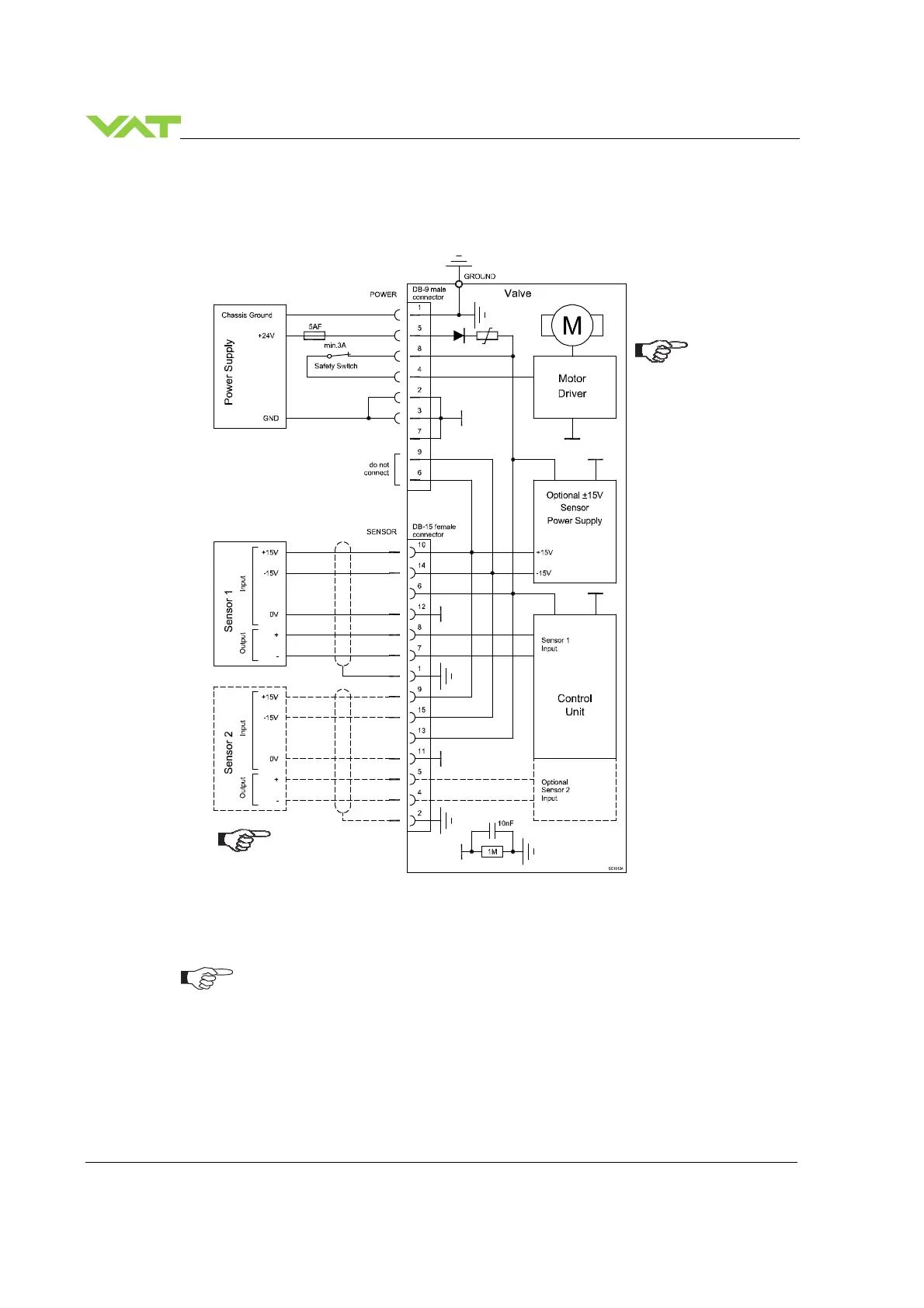
4.4.5 Power and sensor connection (±
±±
±15 VDC sensors) with optional SPS module
[651 . . - . . A . - . . . . / 651 . . - . . C . - . . . . versions only]
•
Use shielded sensor cable(s). Keep cable as short as possible, but locate it away
from noise sources.
•
Connect Power supply (+24 / GND) at DB–9 male power connector and Sensors
(+15V / -15V / 0V / + / -) at DB–15 female sensor connector exactly as shown in
the drawing above!
•
Connector: Use only screws with 4–40 UNC thread for fastening the connectors!
Pins 4 and 8 must be
bridged for operation.
An optional switch
would allow for motor
interlock to prevent
valve from moving.
Low range sensor may be
connected to sensor 1 or
sensor 2 input. Do
configuration accordingly.

 Loading...