XTi- VBox Android TV Gateway User
Manual 2. Connecting XTi-VBox TV Gateway to your Home Network
2.4. Front Panel
3
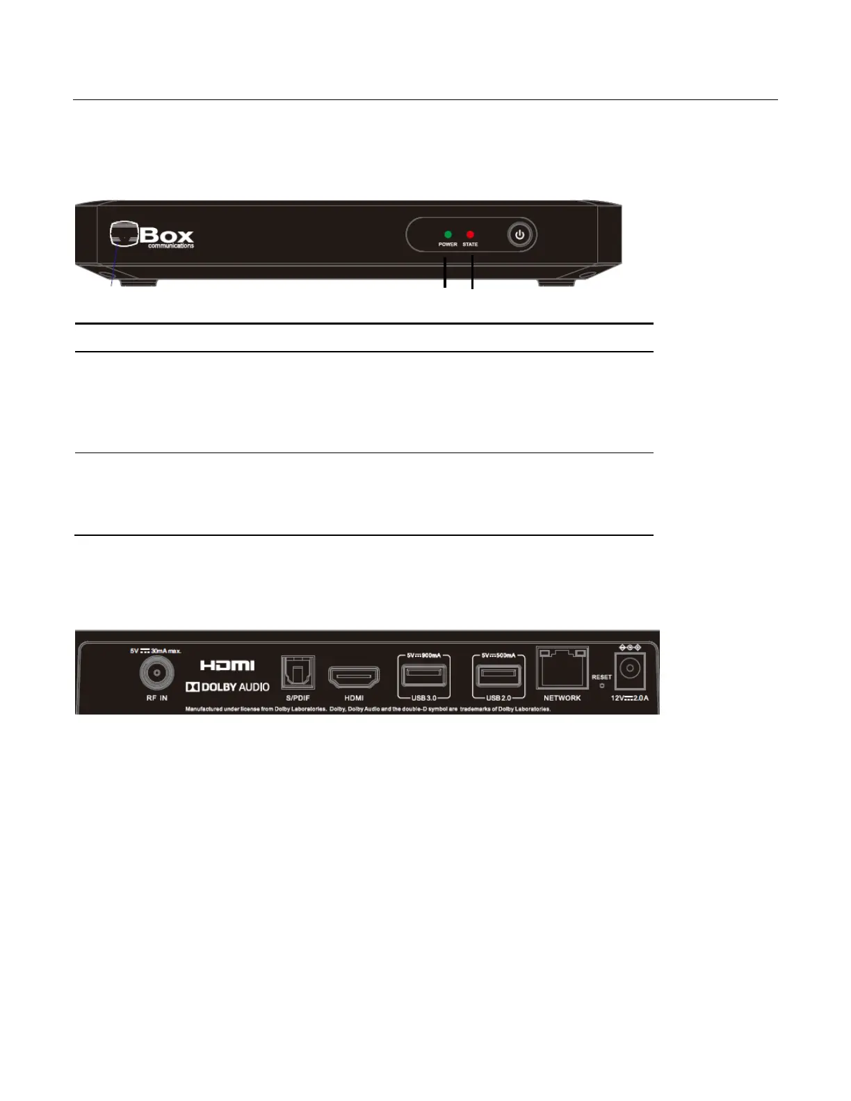
2.4 Front Panel
All XTi-VBox TV Gateway products share the same front panel, illustrated in Figure 1.
Figure 1: XTi Front Panel
2.5 XTi – 4144/74 set up RF connectors
Figure 2: XTi Rear Panel
2.5.1 XTi-4144/74 Rear Panel
The XTi-4144/74 model includes 1 active RF connectors that feeds 4 tuners
Power LED– indicates whether the system is ready:
Orange–indicates the system is connected to electricity
but is still in the process of being started.
Green– indicates the XTi device is ready for use.
STATE LEDs – indicate the traffic status in tuners 1-4:
Steady green light– indicates a locked frequency.
Blinking green light– indicates this tuner is transmitting data.