Connecting the IP Phone 2-2
Chapter 2: Installing the IP Phone
Edge 5000 Installation / Configuration Guide
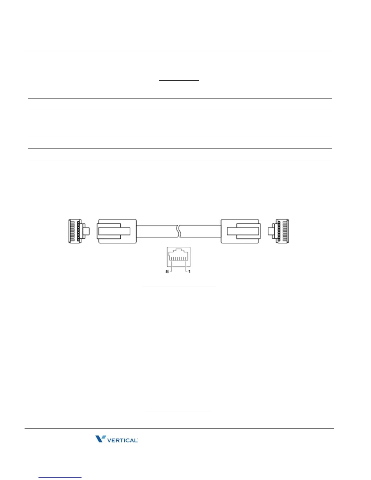
Wiring Chart
RJ-45 Pin Assignments
RJ-45 Termindations
1 LAN Connect the IP Phone LAN port to the LAN wall jack with the provided LAN cable.
2 PC Connect the IP Phone PC port to your desktop PC with an RJ-45 terminated UTP-5 cable.
3 Power If the LAN port supports PoE, IEEE 802.3af compliant, Class 2, the AC/DC adapter is not
required. If not supported, connect the IP Phone power port to the DC out of Power Adapter.
Connect the Power Adapter AC plug to an AC wall jack.
4 Headset Connect Headset RJ-11 jack to the IP Phone headset jack.
5 Handset Connect the Handset coiled cord to the IP Phone base and handset.
6 Exp.
Module
Connect cable provided with the Expansion Module to IP Phone before power is applied, see
"Connecting a DSS Ex[sndion Module".
LAN port PC port
Pin 1 = TX+ Pin 1 = RX+
Pin 2 = TX- Pin 2 = RX-
Pin 3 = RX+ Pin 3 = TX+
Pin 4 = optional: 48V (or GND) Pin 4 = No connection
Pin 5 = optional: 48V (or GND) Pin 5 = No connection
Pin 6 = RX- Pin 6 = TX-
Pin 7 = optional: GND (or 48V) Pin 7 = No connection
8 = optional: GND (or 48V) Pin 8 = No connection