REV : 5
REV DATE : 6/19
DPN002034
Page :1 /1
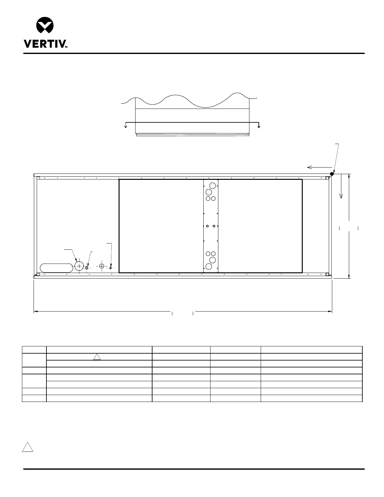
DOWNFLOW MODELS CW076 & CW084 W/ EC FANS
Form No.: DPN001040_REV4
PRIMARY CONNECTION LOCATIONS
LIEBERT CW
FRONT VIEW
A
A
35"
889mm
99"
2514mm
FRONT OF UNIT
SECTION A-A
CD
HUM
CWP
HV
LV
0
X
Y
ALL DIMENSIONS FROM
REAR CORNER OF UNIT
INCLUDING PANELS
POINT DESCRIPTION X Y CONNECTION SIZE / OPENING
CONDENSATE DRAIN 76 3/8" (1940mm) 30 7/8" (784mm) 3/4" (19mm) NPT Female
W/OPTIONAL CONDENSATE PUMP 76 3/8" (1940mm) 30 7/8" (784mm) 1/2" (13mm) O.D. Cu
HUM HUMIDIFIER SUPPLY LINE 73 7/16" (1865mm) 31 7/16" (799mm) 1/4" (6mm) O.D. Cu
CHILLED WATER PIPING SLOT (CENTER) 91 3/8" (2321mm) 31 3/8" (797mm) 101 5/16"(277mm) X 2 15/16"(74mm)
SUPPY & RETURN PIPING DIAMETER - - 2 1/8" (54mm)
HV HIGH VOLT ELECTRICAL CONNECTION 83 7/8" (2130mm) 30 7/8" (784mm) 3" (76mm)
LV LOW VOLT ELECTRICAL CONNECTION 81 3/8" (2067mm) 31 7/16" (799mm) 7/8" (22mm)
CD
CWP
Notes:
1. Drawing not to scale. Tolerance on all piping dimensions is ± (13mm) 1/2".
2. Field pitch Condensate Drain line a minimum of 1/8" (3.2 mm) per foot (305 mm). All units contain a factory installed condensate trap. Do not trap
external to the unit. Select appropriate drain system materials. The drain line must comply with all local codes.
2
Blower
Outlet
Blower
Outlet
 Loading...