REV : 5
REV DATE : 6/19
DPN002035
Page :1 /1
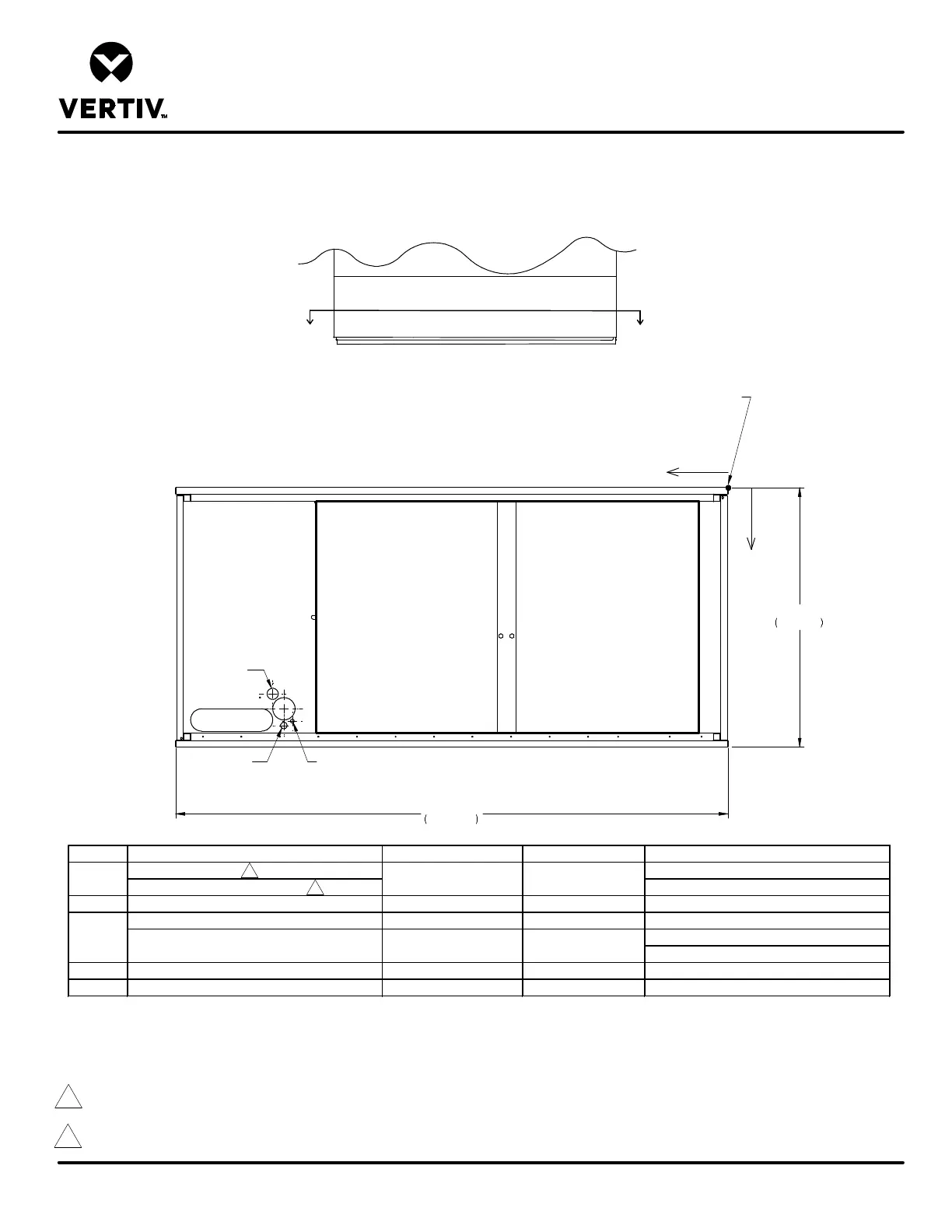
DOWNFLOW MODELS CW051 & CW060 W/ EC FANS
Form No.: DPN001040_REV4
PRIMARY CONNECTION LOCATIONS
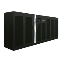
LIEBERT CW
FRONT VIEW
A A
FRONT OF UNIT
SECTION A-A
X
Y
ALL DIMENSIONS FROM
RIGHT REAR CORNER OF UNIT
WITH PANELS ASSEMBLED
0
CD
LV
HV
CWP
35"
889mm
74"
1880mm
POINT DESCRIPTION X Y CONNECTION SIZE / OPENING
CONDENSATE DRAIN 3/4" (19mm) NPT Female
W/OPTIONAL CONDENSATE PUMP 1/2" (13mm) O.D. Cu
HUM HUMIDIFIER SUPPLY LINE 58 3/8" (1484mm) 31 7/16" (799mm) 1/4" (6mm) O.D. Cu
CHILLED WATER PIPING SLOT (CENTER) 66 1/2" (1690mm) 31 1/4" (794mm) 11"(279mm) X 3"(76mm)
CW051: 1 5/8" (41mm)
CW060: 2 1/8" (54mm)
HV HIGH VOLT ELECTRICAL CONNECTION 59 1/2" (1512mm) 29 3/4" (756mm) 3" (76mm)
LV LOW VOLT ELECTRICAL CONNECTION 59 1/2" (1512mm) 32" (813mm) 7/8" (22mm)
CD 61" (1550mm) 27 3/4" (705mm)
CWP
SUPPLY & RETURN PIPING DIAMETER - -
HUM
Notes:
1. Drawing not to scale. Tolerance on all piping dimensions is ± (13mm) 1/2".
2. Field pitch Condensate Drain line a minimum of 1/8" (3.2 mm) per foot (305 mm). All units contain a factory installed condensate trap. Do not trap
external to the unit. Select appropriate drain system materials. The drain line must comply with all local codes.
3. Optional Condensate Pump to be installed under unit.
2
3
Blower
Outlet
Blower
Outlet
 Loading...