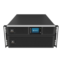
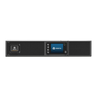
3.4 Installing External Battery Cabinets
Optional, external battery cabinets (EBC) may be connected in parallel to the UPS to provide additional battery run time. For
approximate battery run times with additional EBCs, see Battery Run Times on page70. External battery cabinets are placed
on one side of the UPS in a tower configuration or stacked beneath the UPS in a rack configuration. Up to 10 EBCs may be
connected to the UPS, and up to 6 may be detected using EBC auto-detection.
For applications where the number of EBCs exceeds 6 or for legacy applications where EBC auto-detection is not possible,
please contact Vertiv service for assistance.
WARNING! Risk of electric shock. Can cause injury or death. Disconnect all local and remote electric power
supplies before working with the UPS. Ensure that the unit is shut down and power has been disconnected
before beginning any maintenance.
CAUTION: The external battery cabinets are heavy, see Table 8.4 on page69. Take proper precautions when
lifting them.
To install the EBCs:
1. Inspect the EBC for freight damage. Report damage to the carrier and your local dealer or Vertiv representative.
2. For tower installation:
• An additional set of support-base extensions ships with each EBC.
• See the steps in Tower Installation on the previous page, to connect the support extenders and install the
bases.
- or –
3. For rack installation:
• Rack-mount hardware ships with the EBC.
• Refer to the instructions included with the rack-mount kit to install.
NOTE: Optional slide rails and securing hardware are sold separately. Please contact your Vertiv representative for
options and Vertiv Technical Support for assistance.
4. Verify that the EBC breaker is in the Off position.
5. Connect the supplied EBC cables to the rear of the cabinet, then to the rear of the UPS, see Figure 3.2 on the
next page.
6. Turn the EBC breaker to the On position.
7. Verify the circuit breaker on the EBC is in the On position.
The additional back-up run time is now enabled.
NOTE: When removing an EBC, turn off the circuit breaker on the rear of the cabinet before disconnecting the cable.
NOTE: If shipping or storing the UPS for an extended time, disconnect the EBCs to minimize stand-by current drain on
the batteries and help maintain design life.
3 Installation Proprietary and Confidential ©2024 Vertiv Group Corp. 21
Vertiv™ Liebert® GXT5 UPS Installer/User Guide

 Loading...


