3.5 Installing a Power Distribution Box
WARNING! Risk of electric shock. Can cause equipment damage, injury and death. Before beginning
installation, verify that all external overcurrent protection devices are open (Off), and that they are locked
out and tagged appropriately to prevent activation during the installation, verify with a voltmeter that power
is Off and wear appropriate, OSHA approved personal protective equipment (PPE) per NFPA 70E. Failure to
comply can cause serious injury or death. Before proceeding with installation, read all instructions. Follow all
local codes.
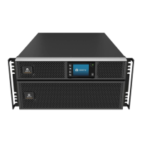
The 5 kVA to 10 kVA models ship with a removable power distribution box (POD) installed, see Terminal Block Connections
on the next page, to make the electrical connections to the UPS. For removal, see the appropriate procedures in Maintenance
on page57.
NOTE: Do not operate the UPS with the POD removed. To shut off all power to the POD and to the load, utility input
power must be disconnected.
3.6 Hardwired Input/Output Connections
WARNING! Risk of electric shock. Can cause equipment damage, injury and death. Before beginning
installation, verify that all external overcurrent protection devices are open (Off), and that they are locked-
out and tagged appropriately to prevent activation during the installation, verify with a voltmeter that power
is Off and wear appropriate, OSHA approved personal protective equipment (PPE) per NFPA 70E. Failure to
comply can cause serious injury or death. Before proceeding with installation, read all instructions. Follow all
local codes.
Observe the following guidelines and specifications when making the hard-wire input and output connections:
• We recommend installing a Class D UL489 approved breaker upstream of unit.
• Provide circuit breaker protection according to local codes. The mains disconnect should be within sight of the
UPS or have an appropriate lock-out.
• Maintain service space around the UPS or use flexible conduit.
• Provide output distributions panels, circuit breaker protection, or emergency disconnects according to local
codes.
• Do not install input and output wiring in the same conduit.
3.6.1 Branch Circuit Breaker
The installer must provide an upstream branch circuit breaker, see Table 3.2 on page25, for the ratings. The input circuit
breaker on the distribution box and the output circuit breaker on the rear of the power distribution box disconnect all power
between the main cabinet and the distribution box. Figure 3.3 on the next page, shows a diagram of the circuit breakers.
Observe the following guidelines and specifications when making the hard-wire input and output connections:
• Provide circuit breaker protection according to local codes. The mains disconnect should be within sight of the
UPS or have an appropriate lock-out.
• Maintain service space around the UPS or use flexible conduit.
• Provide output distributions panels, circuit breaker protection, or emergency disconnects according to local
codes.
3 Installation Proprietary and Confidential ©2024 Vertiv Group Corp. 23
Vertiv™ Liebert® GXT5 UPS Installer/User Guide

 Loading...


