Table 3.2 below details the electrical connection specifications.
UPS Model
Recommended External Circuit
Breaker
Recommended Wire Size
(Including Ground Wire) (75°C
Copper Wire)
Maximum Wire Size Accepted
by Terminal Block
Terminal Tightening
Torque
GXT5-5000HVRT5UXLN 50 A 8 AWG
6 AWG 20 in.-lb (2.26 Nm)GXT5-8000HVRTUXLN 60 A
6 AWG
GXT5-10KHVRT5UXLN 70 A
Table 3.2 Terminal Block Electrical Specifications
To make the terminal-block connections:
1. Loosen the screws from the cable-entry/conduit box cover and pull the cables through the knockout leaving
some slack for connection.
NOTE: We recommend using the knockouts to install input and output wiring in separate conduit. You must use a
suitable cable gland or risk electric shock.
2. Referring to the appropriate terminal-block connection instructions, connect the cables to the corresponding
input/output terminals and use a torque wrench to turn the screw clockwise until tightened as specified in Table
3.2 above. Refer Connecting to Terminal Blocks on 5 kVA, 8 kVA, and 10 kVA models below.
3. Re-install the cable-entry/conduit-box cover and tighten the screws.
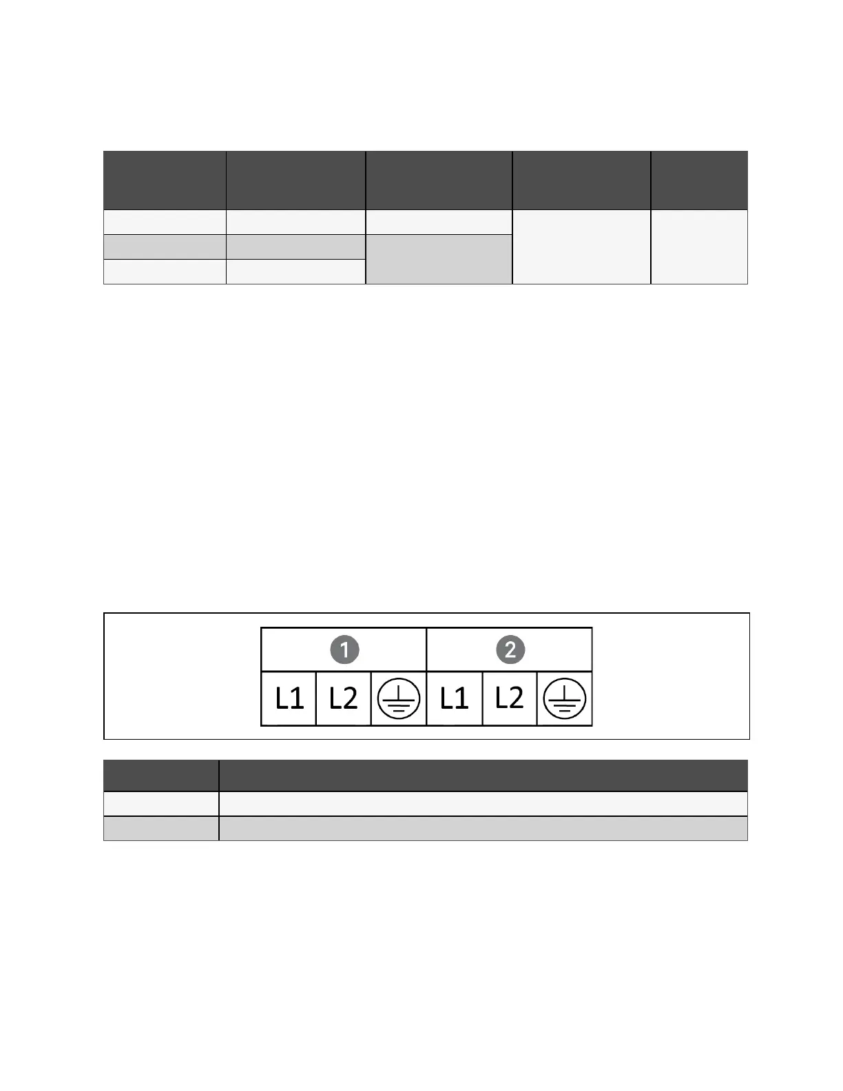
3.6.3 Connecting to Terminal Blocks on 5 kVA, 8 kVA, and 10 kVA models
These models offer a single type of I/O connection, 1-in 1-out common source. Figure 3.4 below, shows the terminal block.
Refer to the details in Terminal Block Connections on the previous page, when making the connections.
Figure 3.4 Terminal Block 5 kVA, 8 kVA, and 10 kVA Models
Item Description
1 Output
2 Input
3.7 Communication Connections
The UPS offers several communication interfaces and ports.
NOTE: We recommend that signal cable lengths be less than 10 ft (3 m) and are kept away from power cabling.
3 Installation Proprietary and Confidential ©2024 Vertiv Group Corp. 25
Vertiv™ Liebert® GXT5 UPS Installer/User Guide
 Loading...