Figure 3.8 Terminal Block
Item Description
1 Output
2 Input
3.10 Communication Connection
The UPS offers several communication interfaces and ports.
NOTE: We recommend that signal-cable lengths be less than 10 ft (3 m), and are kept away from power cabling.
3.10.1 Connecting Liebert® lntelliSlot™ Communication
The Liebert® lntelliSlot™ RDU101 provides SNMP monitoring of the UPS across the network and/or building management
system.
See the appropriate figure for your model in Rear Panels on page4, for the location of the card port.
To install an Liebert® lntelliSlot™ Card:
1. Remove the screws from the slot cover plate and remove the plate.
2. Insert the card into the slot, and secure with the screws that held the cover plate.
To make connections to the card, refer to the Installer/User Guide for the appropriate lntelliSlot card available at
www.Vertiv.com.
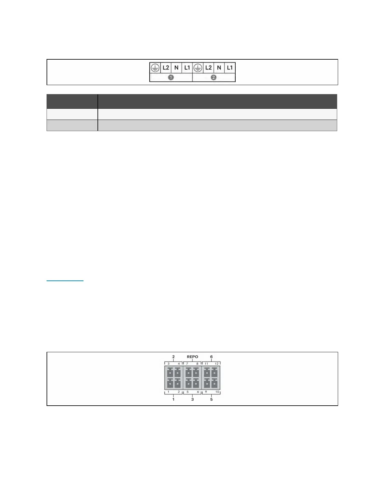
3.10.2 Connecting to the Dry Contact Port
The UPS includes a dry contact port. See the appropriate figure for your model in Rear Panels on page4, for the location of
the port. Figure 3.9 below, shows the ports and Table 3.3 on the next page, describes each port.
The I/0 dry contact port capacity is 125 VAC, 0.5 A; 30 VDC, 1 A.
Figure 3.9 Dry Contact Port and Pin Layout
NOTE: Pins 7 and 8 are shorted before delivery.
3 Installation Proprietary and Confidential ©2024 Vertiv Group Corp. 27
Vertiv™ Liebert® GXT5 UPS Installer/User Guide

 Loading...