Vertiv™ | Liebert® LDMF™ Distribution Monitoring User Manual | 10
4.0 INSTALLATION
This section provides instructions for installing and connecting Liebert LDMF current
transformers. If any Liebert LDMF component requires service, contact Vertiv Support at
800-543-2378 for assistance.
4.1 Installing a BSM (CT Module Assembly)
In most cases the BSM—the CT Module—is factory-installed and no further work is required. If a
CT Module must be added, it attaches easily to the side of a panelboard to monitor any
combination of 1-, 2- and 3-pole circuit breakers.
• For side-by-side panelboards (21 circuits on each side), attach one CT Module
to each side of the panelboard, ensuring that the center of the CT hole lines up
to the branch circuit breaker connection.
• For Square-D Inline panelboards (42 circuits in a row), the two CT second, lower
CT Module so that the two cutout sections line up, then attach the screws to
secure the CT Modules to the panelboard.
• For GE Inline type panelboards, the two CT Modules fit end to end. Flip the
second, lower CT Module so that the 50-pin ribbon cable connector, mounted
on the bottom of the CT Module, lines up with the hole in the panelboard
mounting bracket.
Install the circuit breakers according to the manufacturer's
documentation. Route the circuit wire through the center of the CT and
attach securely to the circuit breaker.
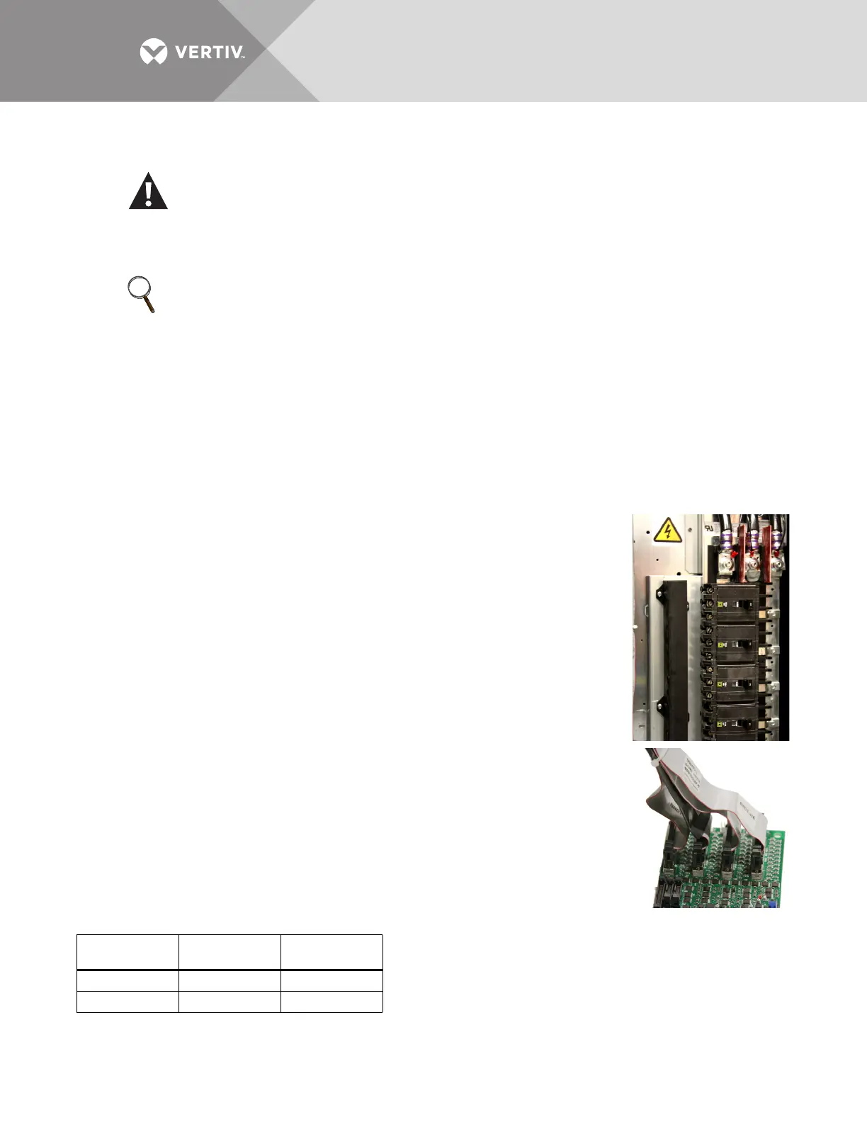
4.1.1 Connecting Panelboards A and B
The CT Module connects to the PMB via a 50-pin ribbon cable attached
to the back of the CT Module. Route the ribbon cable and attach to the
appropriate connector (see figure at right).
There are four connectors that are labeled for easy identification: two for
Panelboard A (A1 and A2) and two for Panelboard B (B1 and B2).
• Connect the CT module that will monitor Circuits 1-21 to the A1 or B1
connector, depending on whether the CT Module is monitoring Panelboard A
or B.
• Connect the CT module that will monitor Circuits 22-42 to the corresponding A2 or B2 connector.
WARNING
Dangerous voltages exist in power distribution units and power conditioning units. To
ensure maximum safety, all circuits breakers in the panelboard should be removed of power
and the input feeder breaker should be turned Off and locked-out in accordance with NEC
and local/state code.
NOTE
Liebert LDMF components and any other monitoring devices should be installed only by properly
trained and qualified personnel.
Circuits
Monitored
Panelboard A
Connector
Panelboard B
Connector
1-21 A1 B1
22-42 A2 B2