Vertiv™ | Liebert® LDMF™ Distribution Monitoring User Manual | 12
4.3 Installing a Current Transformer on the PIB Interface Board
If subfeed breakers are ordered with the unit, the phase,
neutral and ground CTs are wired to the Interface
Board.The CTs will be zip-tied inside the equipment for the
electrician to install on each conductor when the
conductors are wired to the subfeed/large branch breaker.
The ground and neutral CTs for each factory-supplied
subfeed or large breaker are factory-installed and wired.
CTs have a white or H1 that depicts how to position the CT
on the cable to ensure accurate readings. The white dot or
H1 must face toward the source when installing the CT on
the phase cables. The neutral conductor CTs are placed in
the opposite direction, with the marking faced toward the load. Route the conductors through the
core of the CTs and wire-tie the CT to the cable to ensure the CT stays in place.
If subfeed breakers are installed in the field, up to five CTs may be installed (three phases, neutral
and ground). The neutral and ground CTs may be omitted if monitoring of neutral and ground is
not required. The 5-wire CT kits will be shipped separately and grouped together with each CT
with a label indicating whether it is a phase CT, neutral CT or ground CT.
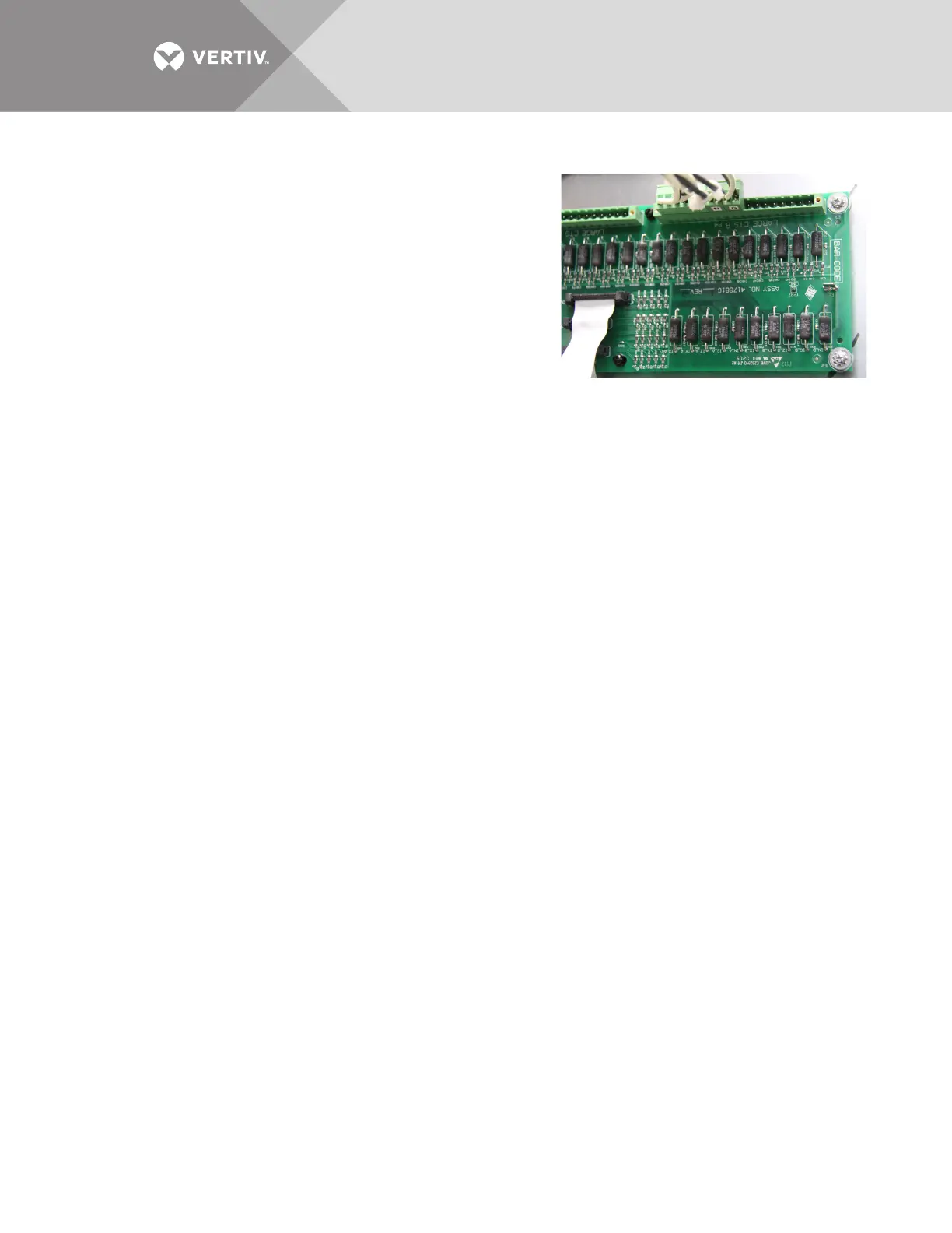
There are two 18-pin terminal blocks on the Interface Board for large branch circuit breakers
and/or subfeeds-one for Panelboard A and one for Panelboard B.
The circuit board is marked with a triangle to indicate Pin 1. Pin 1 should be used for the white wire
of CT1 (Phase A). The black wire should be connected to Pin 2. The same pattern will follow for
the remaining CTs.
After all CTs are installed, use the Configuration tool to label and set alarm parameters. To
configure the Liebert LDMF, see 5.5.11 - Add a Circuit Breaker.
If the Power Distribution Center is supplied with optional isolated ground, the isolated ground
circuit can be monitored by the Liebert LDMF. Usually the CT is already installed and wired to the
Large Branch Terminal Block at the factory. If not, perform the following steps:
(For Isolated Ground CT Installation only)
• Connect the isolated ground CT to Pins 17 and 18 on the two 18-pin terminal blocks on the Interface
Board.
• Connect the isolated ground CT white wire to Pin 17 and the CT black wire to Pin 18.
Refer to the following example and Table 2 for wiring configuration details.
Example: When installing a subfeed breaker where the three phases, neutral and ground will be
monitored, the CTs should be wired as follows: