Vertiv™ | Liebert® LDMF™ Distribution Monitoring User Manual | 16
4.4 Connecting a Current Transformer to the PM4 Large Interface Board
(PLIB)
PLIB can monitor eight 4-wire or 5-wire output/subfeed breakers. Two LIB boards are provided to
support up to 16 output and/or subfeed breakers. If subfeed breakers are ordered with the unit,
the phase CTs are installed and wired to the PLIB. The neutral and ground CTs are also factory-
supplied and wired to the PLIB as required.
CTs have a white dot or H1 marking that depicts how to position the CT to ensure accurate
readings. The white dot or H1 marking must face toward the load when installing the CT on the
ground and neutral cable. The phase CT's are placed in the opposite direction, with the marking
faced toward the source. Route the neutral and ground cable through the core of the specified CT
and wire-tie the CT to the cable.
If subfeed breakers are installed in the field, up to five CTs may be installed to monitor a subfeed
breaker (three phases, neutral and ground). The neutral and ground CTs may be omitted if
monitoring of neutral and ground is not required.
The designators on the PLIB are different from those on the Interface Board.
• CT1 (Phase A white wire) begins on TB1 CT1+ and the black wire connects to CT1-.
• The Ground CT for the first subfeed/output circuit breaker connects to TB4 CT35.
The designators on the PLIB are different from those on the Interface Board.
• CT1 (Phase A white wire) begins on TB1 CT1+ and the black wire connects to CT1-.
• The Ground CT for the first subfeed/output circuit breaker connects to TB4 CT35.
If more output or subfeed CTs must be installed, continue in the same pattern shown above.
• Connect the Phase A CT for the second breaker on CT5 (white wire to CT5+, black to CT5-).
• Connect the Ground CT for the second breaker to CT36 (white wire to CT36+, black to CT36-).
• Continue the same pattern until all CT connections are used or there are no more outputs or subfeed CTs
to add.
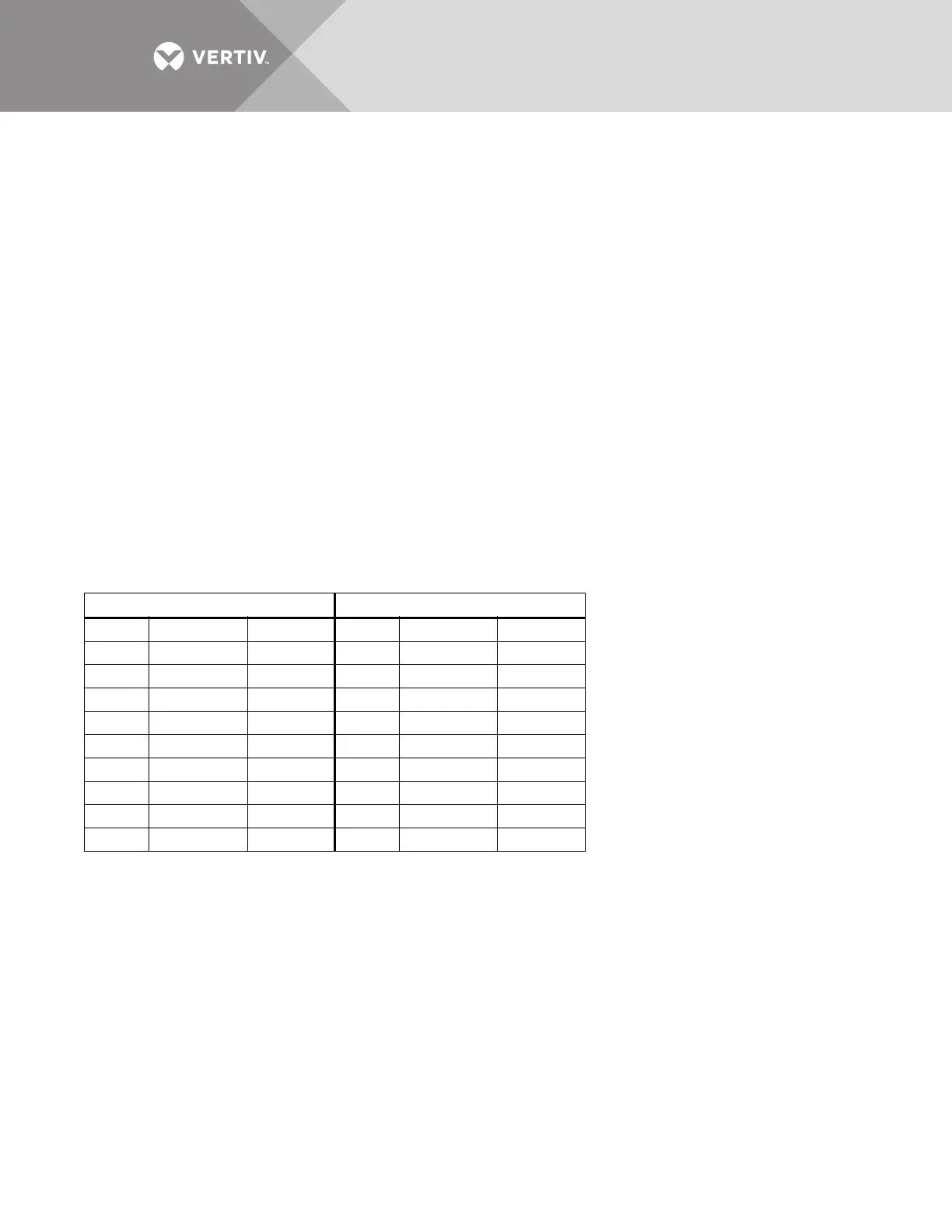
First Breaker Second Breaker
CT1+ Phase A CT White wire CT5+ Phase A CT White wire
CT1 Phase A CT Black wire CT5 Phase A CT Black wire
CT2+ Phase B CT White wire CT6+ Phase B CT White wire
CT2 Phase B CT Black wire CT6 Phase B CT Black wire
CT3+ Phase C CT White wire CT7+ Phase C CT White wire
CT3 Phase C CT Black wire CT7 Phase C CT Black wire
CT4+ Neutral CT White wire CT8+ Neutral CT White wire
CT4 Neutral CT Black wire CT8 Neutral CT Black wire
CT35+ Ground CT White wire CT36+ Ground CT White wire
CT35 Ground CT Black wire CT36 Ground CT Black wire