Vertiv™ | Liebert® LDMF™ Distribution Monitoring User Manual | 4
3.0 MAJOR COMPONENTS
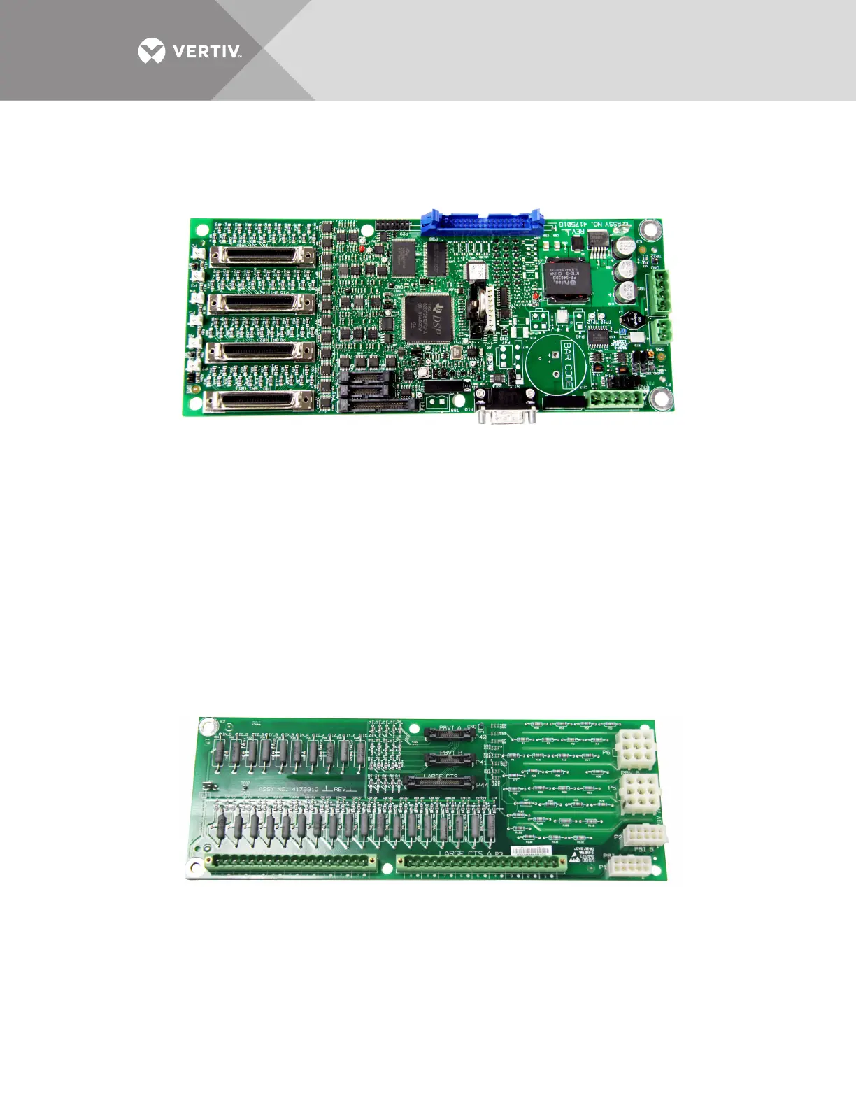
3.1 PM4 Monitor Board (PMB)
The PM4 Monitor Board (PMB) is the main processing and storage circuit board. The PMB
contains the non-volatile memory where the configuration file is stored. The CT Module
Assemblies will connect directly to the PMB via the 4 ribbon cables connectors. The PMB is a
DSP-based logic controller with internal flash memory to store breaker configuration, alarms and
energy data. The on-board battery supplies power to the real-time clock.
All the electrical parameters are accumulated on the PMB for processing to Liebert Velocity
protocol for remote monitoring and the HMI interface for the local display. Kilowatt-hours (kWh)
data is accumulated on this board for the panelboard mains, subfeeds and each branch circuit
breaker. A remote command can be used to reset the accumulated energy data.
Additional PMB Capabilities
• Six (6) auxiliary CT connectors, which allow for replacing a failed CT.
• A DB9 serial port on the outside panel is available for local configuration.
3.2 PM4 Interface Board (PIB)
The Liebert LDMF PM4 Interface Board (PIB) provides connections for the voltage and currents
of the panelboard main circuit breaker as well as the CT current for any installed large branches
or subfeed breakers (maximum of 18 CTs).
For the large branches or subfeed breakers, the nine CTs on the A side of the board are normally
associated with the A-side voltages for power calculations. The B-side CTs are normally
associated with the B-side voltages. A cross-configuration tool allows changing that association
for subfeeds.